These posts cover the CNC router construction and configuration. Some of the material was originally posted in CNCZone in the DIY router builds forum in 2015 and 2016. However, that thread covered only portions of the build and was largely consumed with getting Mach4 (the CNC control software) properly configured and debugged. At that time, Mach4 was less than a year old and I was one of the early (and naive) users. I really wanted the latest control software and skipped over the tried and tested Mach3.
Design and Early Constraints
The CNC router is a moving gantry design with a work area of approximately 60×60 inches. If I clean off the workbench behind it, I can fit an entire 4×8′ sheet but can only work on a bit more than half at a time.
I am built the router with a mix of aluminum extrusions and steel. Structure:
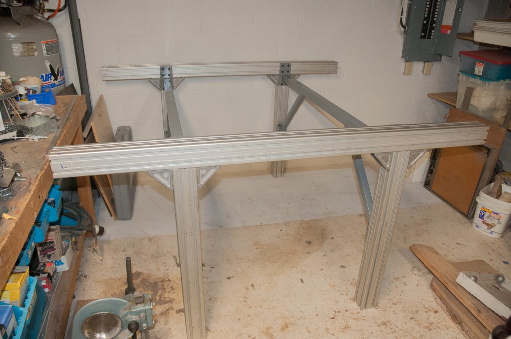
Y Axis beams, legs and risers for the Y carriage are Bosch-Rexroth 9090H. Legs are bolted on with Bosch 90 mm corner brackets. This was material that was salvaged from a test X-ray system that Siemens had made for Camtronics, where I worked, that was to be scrapped after the project that it was for was obsolete. The 9090 pieces had collected dust in my basement for several years.
Welded cross members are 2×2 x 3/16″ . These provide the leg braces in the Y direction. This was welded up by using one of the x axis rails and legs set to the appropriate width as the jig
Y beam / gantry is 6x6x1/4″ 66″ long with 5x 3/8 diagonal steel rods welded in. One of the CNCZone members, Dave Malicky, had done some great analysis of the cross beam bending under load for a variety of configurations and helped out me out with suggestions – CNC Router for Hardwoods: Evaluation and Questions #125. The faces of the gantry are 1×1/4″ HRS that was drum sanded to final thickness and finish and then glued on the beam with West system epoxy and colloidal silica filler. This is to provide a flat surface for the linear motion bearings to run on. The 6×6 structural steel itself is not flat and true enough and I do not have a way to machine it properly to be flat and true (e.g. a large Blanchard grinder). So this is a relatively low tech way to get a flat and true surface on the beam.
Other Cross tubes are 2x2x1/8″ HRS
X and Y linear rails are 15mm NSK
The Y beam / gantry was bolted on today and used to align the front linear rail. The rear rail was the reference, which was aligned to a groove in the x rail extrusion. Overall I have 56″ of x axis travel. Y would end up at about 54″
The gantry moves nicely
Construction
The base sides support the Y axis and these are basically just bolted together. The grey cross bars and diagonals were welded up from tubular and flat steel stock.

Once the basic structure was completed, it was time to tear it down and drill and tap the dozens of holes for the linear rails which had now arrived (from Korea). This was my first attempt at power tapping on the Bridgeport mill. Amazingly, I did not break a single tap while power tapping the many dozens of holes. “Gun” taps which push the swarf out ahead of the tap for the through holes are a wonderful thing. Note the Koolmist spray which cool, lubricates and reduces the friction when drilling and tapping.

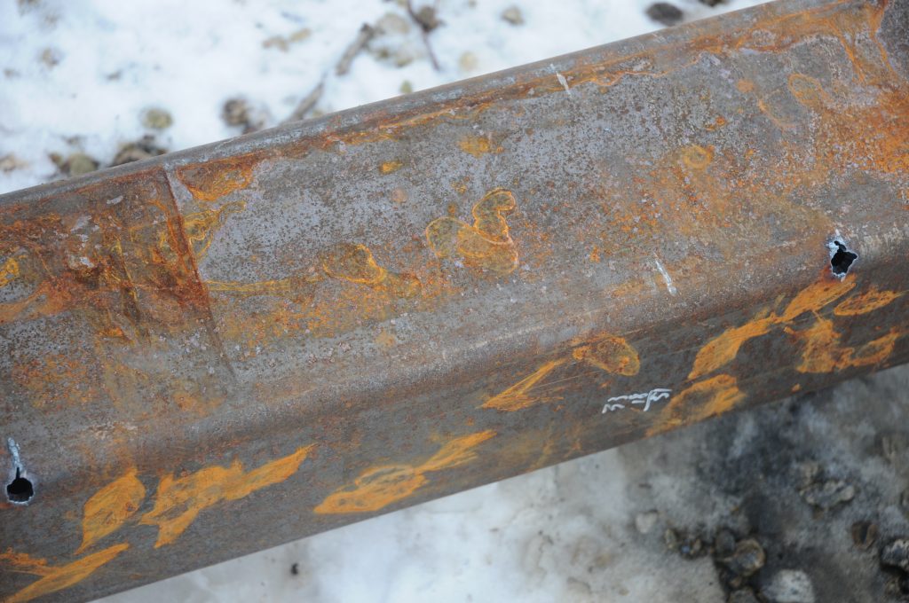
With the base in a reasonably functional state, it was time to focus on the gantry which is the X-axis. The gantry is 6x6x1/4″ thick structural steel tube and is 66″ long. I was able to procure some salvage stock for this (hence the rust and other marks). Given that I want to be able to cut metal and have a decent vertical travel, the flex of the tube under load is a real consideration. One of the CNC zone members at the time was a professor of mechanical engineering who did the analysis. His recommendation was to ad diagonal rods to the tube to control the flex. So that is what I did. Below you can see two of the holes for the rod that was done with the plasma cutter.


The tube was then cleaned up – rust removed and surface blemishes ground out for the most part. The plan was to add some steel strips to one of the faces to then have a clean reference surface for the X axis linear rails. The steel flat stock was run through the thickness sander to provide nice clean surfaces. The steel strips were then to be glued on with epoxy. However, the question was then, where is there a dead flat smooth reference surface about 6 feet long to hold all of this while the epoxy cures? The answer is the bed of my 125+ year old Colladay 16″ jointer.

Now there were a series of choices as to how to align the strips to the tube while manhandling the whole thing into position after applying the epoxy (it is quite heavy – approx 120 lbs). Scrap pieces of 1/4″ plywood were cut (actually more like 5mm thick) to act as spacers. The top of the jointer was covered with wax paper to make for an easy release surface for any stray epoxy.


The cross beam was cleaned up. The holes for the linear rail were then drilled and power tapped. With some paint on, it is test mounted on the Y axis rails. More cross rails were added below the Y axis beams to eventually support the work bed. The X and Y linear rails are 15mm NSK. Note that there are 2 recirculating bearing blocks under each end of the gantry.

