With the main portions of the frame completed, now it is time to add the rest of the drive components.
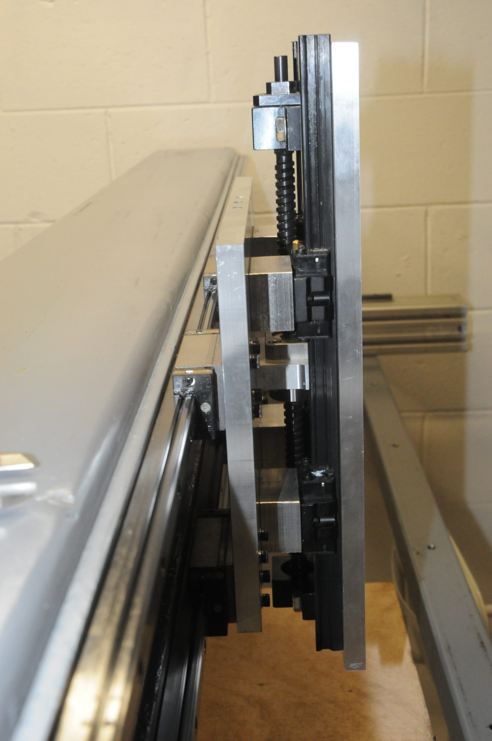
The X axis gets dual 15mm NSK linear rails (NSKLH15BN) 1680mm long. The X axis carriage is mounted to them with 2 bearing blocks per rail. The X axis carriage plate and the Z axis plate are 1/2″ aluminum plate.
The Z axis carriage gets mounted on 15 mm linear rails 356mm long with SX 15-8 bearing blocks 356 mm long. It is driven with a 12mm ground ball screw GTR1205C5+353L ISSOKU EK10+EF10 for the end blocks. The ball screw is mounted in between the X and Z plates. The limit switches are in between as well.
As I was doing this, drilling, tapping and counterboring dozens more holes it felt like I was turning the aluminum plates into Swiss cheese.
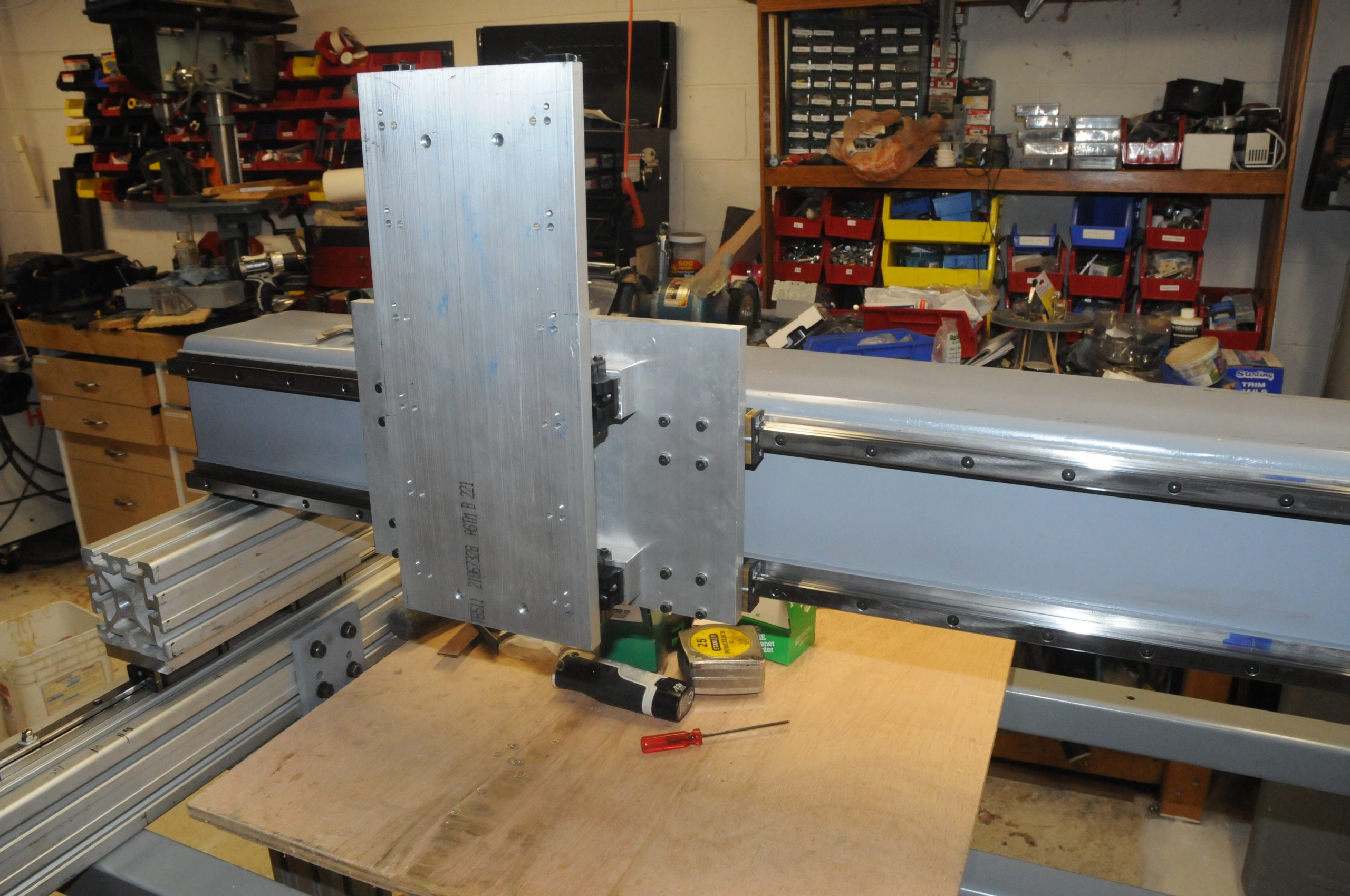
The X carriage was mounted first. At this stage the final alignment of the linear rails could be done. The tolerances for the spacing are tiny and this is most easily done by setting one of the rails in place and then using the carriage basically as a pacer to get the final alignment of the second rail. The carriage was run back and forth a number of times and the process iterated until it ran smoothly and with minimal drag.
Next the Z rails and spacer blocks could be mounted. There are spacer blocks added under the Z rails to provide clearance for the ball screw components. The ball screw is mounted to the Z carriage. This method minimizes the distance the Z carriage must be offset from the X plate as the stepper motor that will drive it can stick up past the Z carriage plate. Then the z carriage was then mounted for the first time. It would need to come off multiple times as more parts are added.
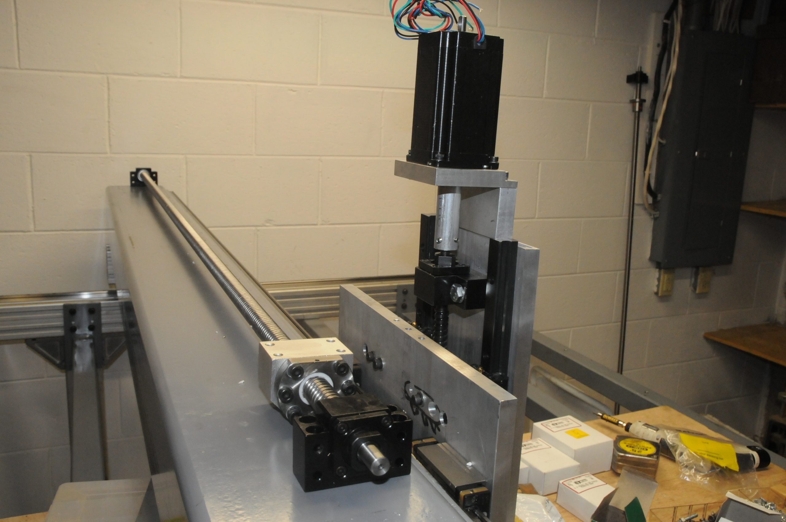
First manual motion of all 3 axes
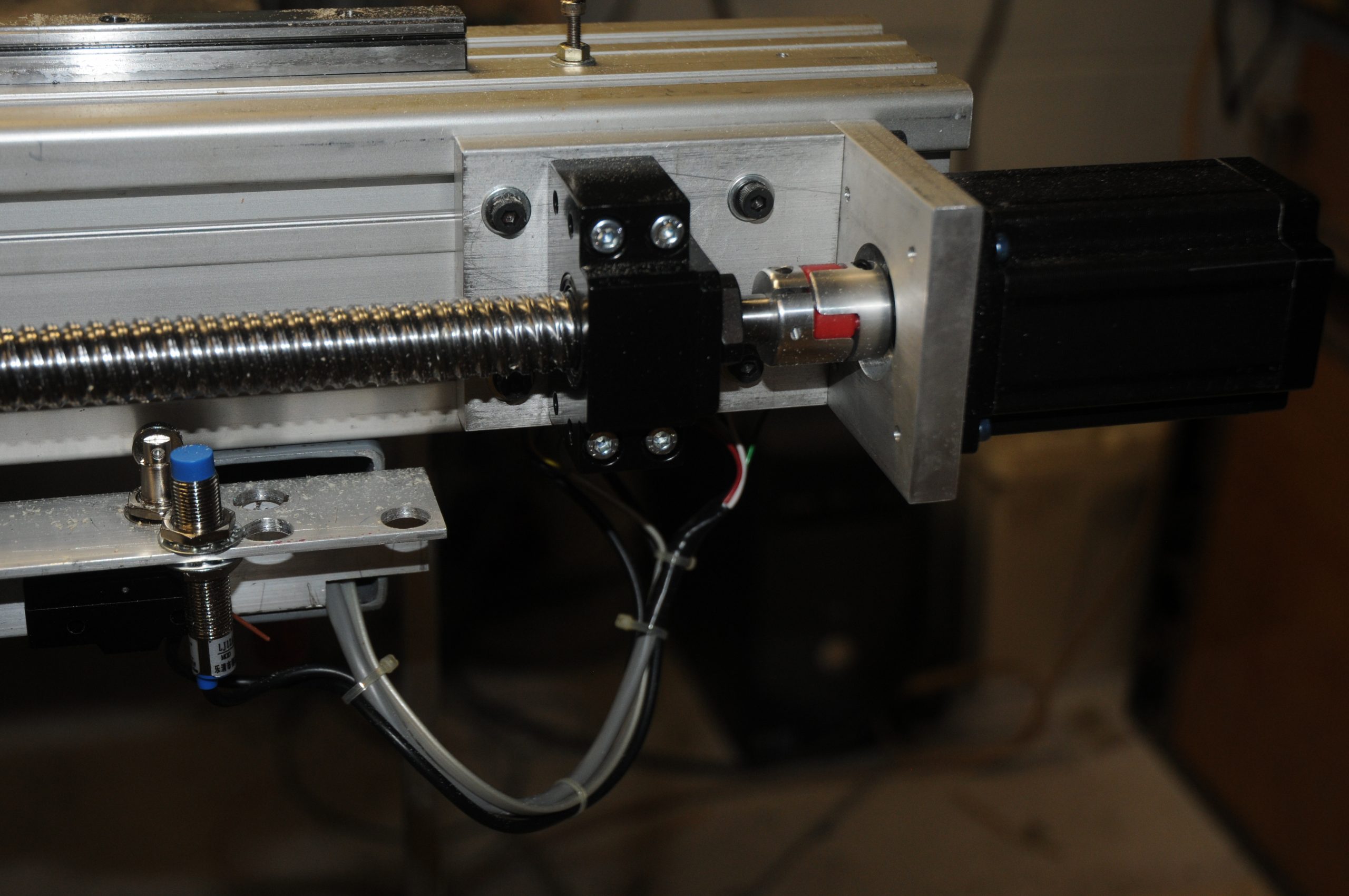
The Z axis stepper drive motor was then mounted on to the carriage and ball screw. I custom made the coupler that was used between the motor and the drive screw.
Next came the X and Y drive screws. These are 20mm diameter 10 mm pitch rolled ball screws for X and Y with dual Y drive. These are double start screws. This means that for each revolution the carriages will move 20mm.
Stepper motors are:
- 380 oz-in Nema 23 for X and Z axes. Low 2.8 mH inductance on the windings. This is plenty strong to lift the carriage with the 2.2KW water cooled spindle installed with power to spare. No need for a gas spring. Low 2.8 mH inductance on the windings.
- 570 oz Nema 23 for Y axis . 2 of these with paralleled windings on each to keep the inductance down (2.7mH , 5A) . This may well have been overkill and the current draw is what pushed me to the next size up in stepper drivers and power supply.
Stepper drivers and power supply:
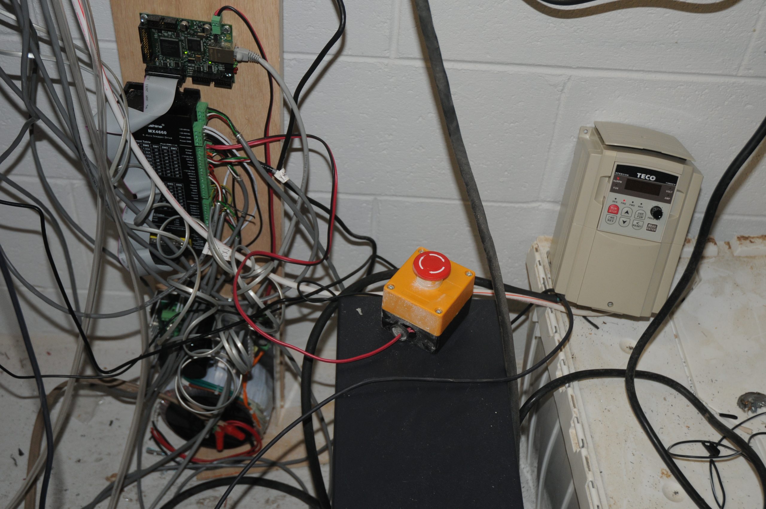
- LeadShine MX 4660 4 axis digital Stepper driver and I/O. This is similar in concept to the Gecko G540 but handles higher current and voltage
- 48v 20 A linear power supply. I went with 48 v to stay within the 60 v rating of the stepper driver. More voltage would have been nice (e.g. 65 v or so) for optimum stepper performance with the inductance these motors have but that would have been one more escalation in price requiring separate high voltage stepper drivers.
When laying out the drive system the lowest cost components are the stepper motors by far. Additionally, going up a “little in size” on the motors is not very expensive. However, to properly drive them and handle the increased current demand and more importantly the increased inductance, the cost of stepper drivers and power supply goes up exponentially.
I agonized over how to balance accuracy, speed, precision and rigidity and still not completely blow the budget. Each “up-size” for a better component demands up-size and more cost of the surrounding components if you are going to take advantage of the improvements and avoid potentially going backwards (too big a stepper with all else equal will NOT go as fast as an appropriately sized one). About the only area that does not push other costs up is building a more rigid base frame (primarily because it does not move).
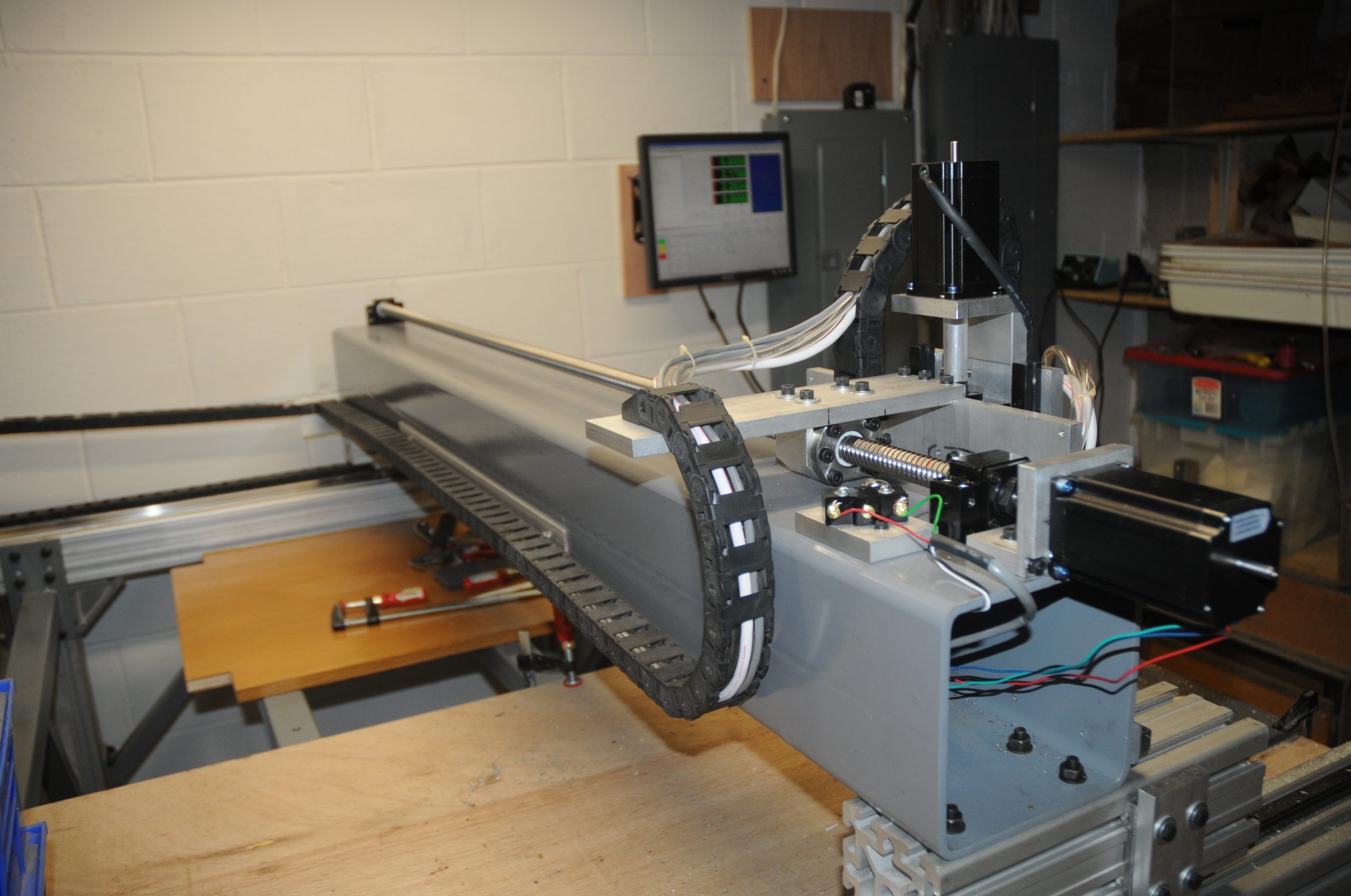
So far with 1750mm long Y screws and 250 ipm rapid moves I see no noticeable whipping (even nothing much to feel). I have not really tried to push faster yet.
When running the mach4 demo roadrunner (cutting air) the whole thing sounds like R2D2 gone mad (almost semi musical).
There are dual drive screws and stepper motors on the Y axis. This is needed to provide the torque required to rapidly move the ~ 300lb gantry and to eliminate twisting of the gantry as it accelerates and reverses. Some folks will say not to do this as there is a danger of the motors losing steps and getting the whole thing out of sync and damaging itself. I am careful in the selection of the components and will test to ensure there are no lost steps within the speed and acceleration limits I will set. This also requires dual homing sensors and dual limit switches – one each for each side. This was a point of considerable consternation as the new Mach 4 control software and the Ethernet Smoothstepper drive board did not fully implement this at the time I built. The software bugs took a couple months more to get worked out.
The router spindle arrived as well. It is a 2.2Kw (~3HP) 400Hz 3 Phase water cooled spindle. This also requires a 3 phase variable frequency drive to power it. This is similar to, but bigger than the ones I use on the Southbend 13″ metal lathe and the Bridgeport mill. I used a Teco 7300.
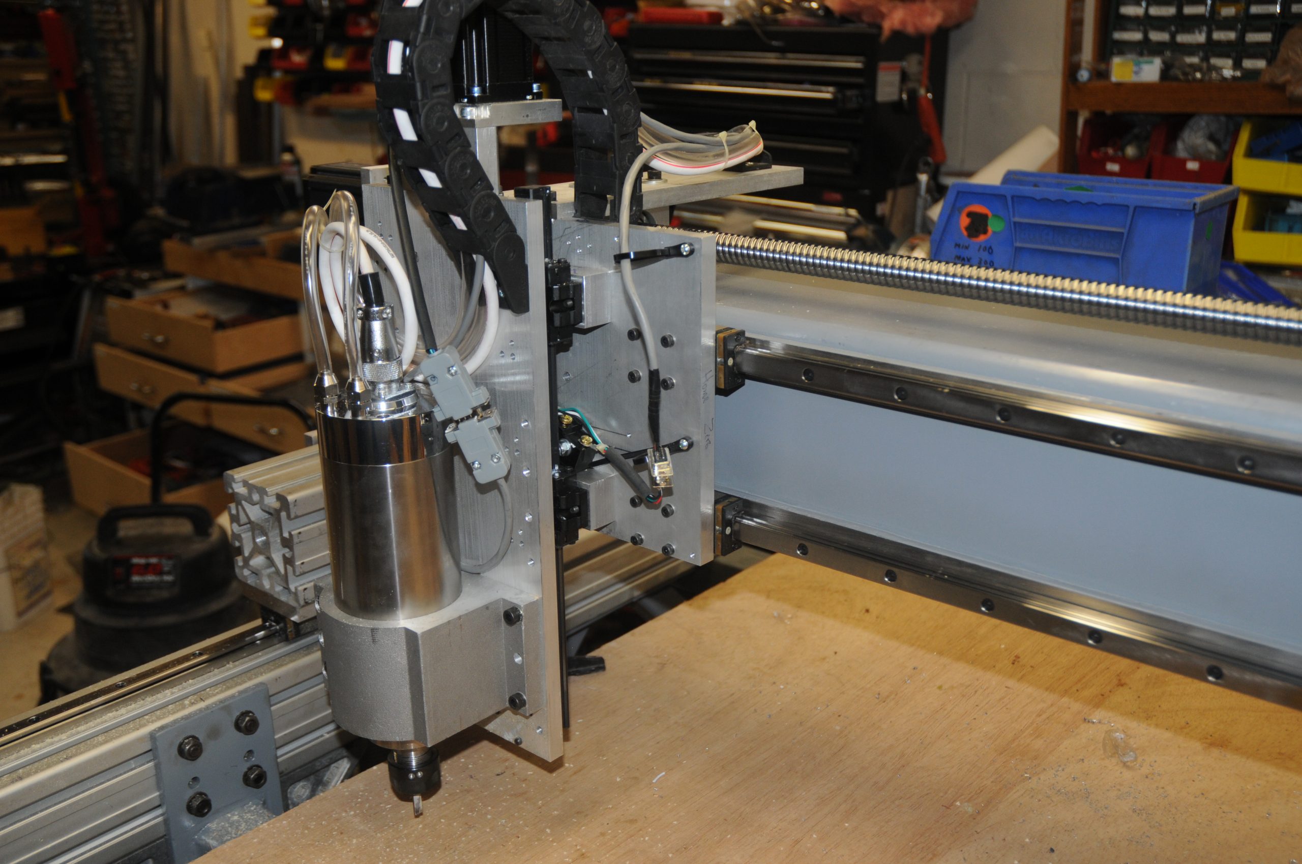
In order to neatly dress all of the the cables and the cooling lines cable chain is needed. This is 15x30mm with removable link covers (I should have gone a size larger).
At this point the system is basically running but the wiring is a “rats nest” where I was connecting things to see if I could get them to work.
At this point the breaker panel is out of space. In order to add the circuit for the VFD and spindle drive I need to add another sub-panel. This is located next to the main breaker panel.
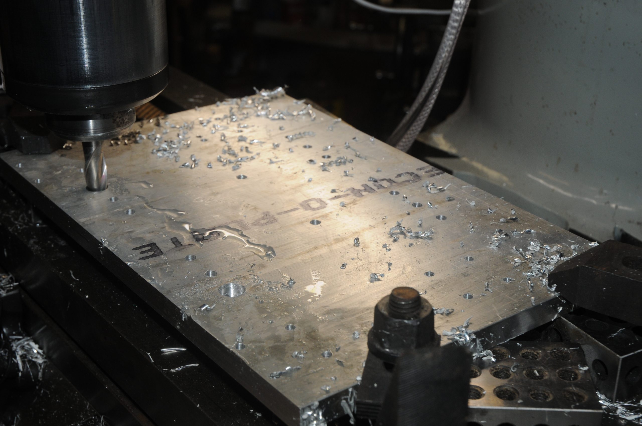
Now with power for the spindle, I can actually make the first test cuts.