
- For some upcoming projects I need to neatly bend sheet metals. In the past I had done this for small “one off” items by blaming in a vise or between some pieces of angle iron or using a “tinners pliers” / metal seamer. However now I needed make dozens of bend that are crisp and repeatable. Options ranged from a full size press brake, sheet metal brake (the type you lever up to fold) or kits to build one to go in my 20 ton arbor hydraulic press. All seemed to be a bit overkill and the tool budget had been going wild lately so I needed to make something with “parts on hand” rather than purchase another tool. Besides I am pretty much out of space for another large tool that would normally get infrequent use.
After reading and watching several youtube videos on brake construction, I had a basic design in mind. The goals being ot keep it simple and use materials on hand:
- ~12″ width / capacity
- “Air bending” with movable die jaws. WIth Air bending there is not a lower die but the metal is pressed down into the gap between some bars / jaws . It can provide nice crisp bends
- Hand operated or able to fit in my bench top arbor press for additional force. This avoided having to build an outer frame and the hydraulic press was too slow
- Fixed blade / upper jaw rather than removable fingers
Digging around in my metal stock / scraps I found some:
- 1.5×1.5×1/8″ steel tubing which would become the top rail.
- 1/4 x 1.5″ steel flat stock for the jaws and blade
- 1/2×5″ steel flat stock for the base
- 1/2″x 6″ bolts that would be the columns
- Springs and miscellaneous hardware
The first step was to shape the edge of the blade on the mill. I used a 3/4″ “corncob” or roughing end mill. The head of the Bridgeport mill was inclined to ~37 degrees. You want the blade edge to be less than 90 degrees to allow for some degree of overbending to allow for spring back . This could be done with a hand held grinder and file instead

Next the top bar was cut and the blade was welded to it. I did my best to center the blade and keep it vertical but there was undoubtedly some error. So to drill the holes for the columns the blade was clamped in the vise. I wanted a close sliding fit to minimize error in the bends and did not have stock for bushings on hand. The holes were then reamed for a decent fit on the bolts with an expandable hand reamer.

Next the holes for the column were drilled in the base plate. The digital readout of the mill helps in setting the exact spacing
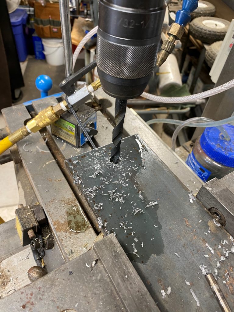
Each hole was hand tapped with a tap follower held in the drill chuck to ensure that the threads were perfectly aligned and the posts would be vertical .
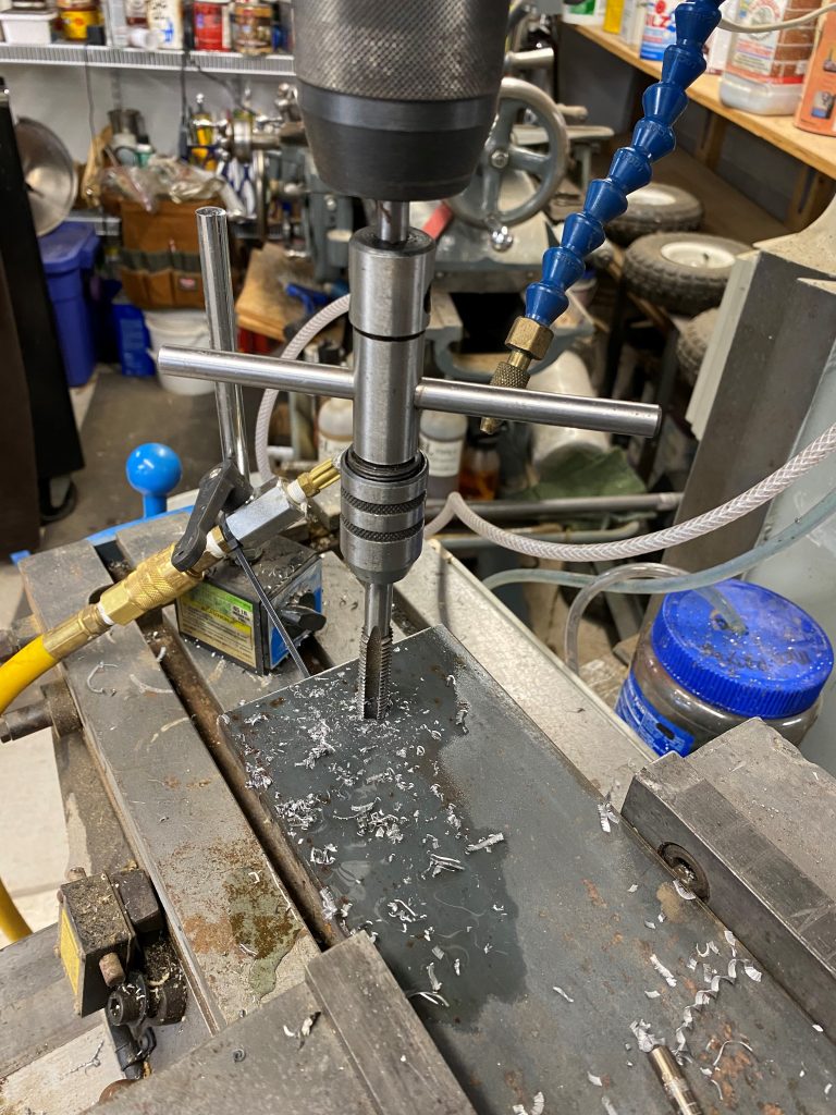
There were also the jaws to make and the holes for them to be drilled and tapped. However for these I have so called “gun taps” that can be power tapped. This is much easier and faster.

The brake was now assembled and the initial tests show it can make nice crisp bends. Depth stops were added after this photo to allow for better repeatability of the bends.