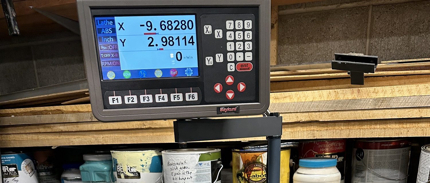
It took a bit of back and forth with the vendor and testing, but it turns out I DID receive 1uM resolution scales that were mis-marked as 5uM. With the DRO configured for 1uM resolution, the scales read correctly (e.g. 75mm movement gives a 75mm change on the display and the display indicates movement down to 0.001mm). The scales are what take the motion and digitally encode the output for the display.
Now it was time to mount the scales. I started with the more difficult one, for the cross slide. As you can see there are basically no straight edges on the cross slide. So the scale needs to be spaced out a bit towards the tailstock to clear the bump for the pivot for the compound. The supplied mounting brackets were not helpful for mounting the scales. The parts were made “to fit” and I did not keep records of the exact measurements.
There is a screw hole near the front that houses a setscrew for the gib. I re-used this to mount the front spacer block. The front spacer block needs to be about 0.7″ thick to space the scale out enough to clear the compound bump. This piece was milled to size, drilled and counter bored for a SHCS (Socket Head Cap Screw and then mounted in place. This end of the scale will be “fixed” and the far end will have the horizontal and vertical adjustment. Only one end really needs to be adjustable and this simplifies the design as well as the alignment.
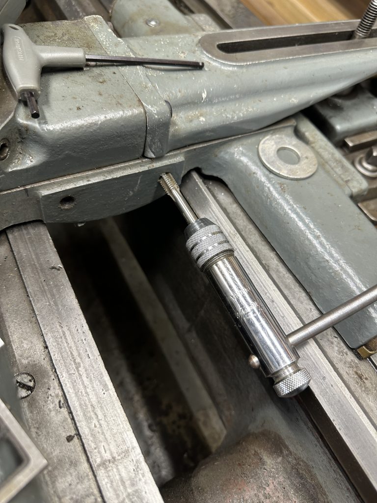
The sliding “reader” will be mounted on a spacer block to 2 existing holes on the lathe saddle. These are normally used for the follower rest. I do not have one and on inspecting the holes it seems doubtful that there was ever one installed on this lathe. I had to dig out 75 years of accumulated gunk from the holes and chase the threads with a tap. There is not much clearance for the tap handle and a ratcheting tap handle really came in handy.
Next I needed to remove the “tail” of the taper attachment to take it to the mill to drill and tap the mounting holes for the blocks that will hold the far end of the scale. The holes are out of the way of the motion of the taper attachment tail and the locking clamp for it.

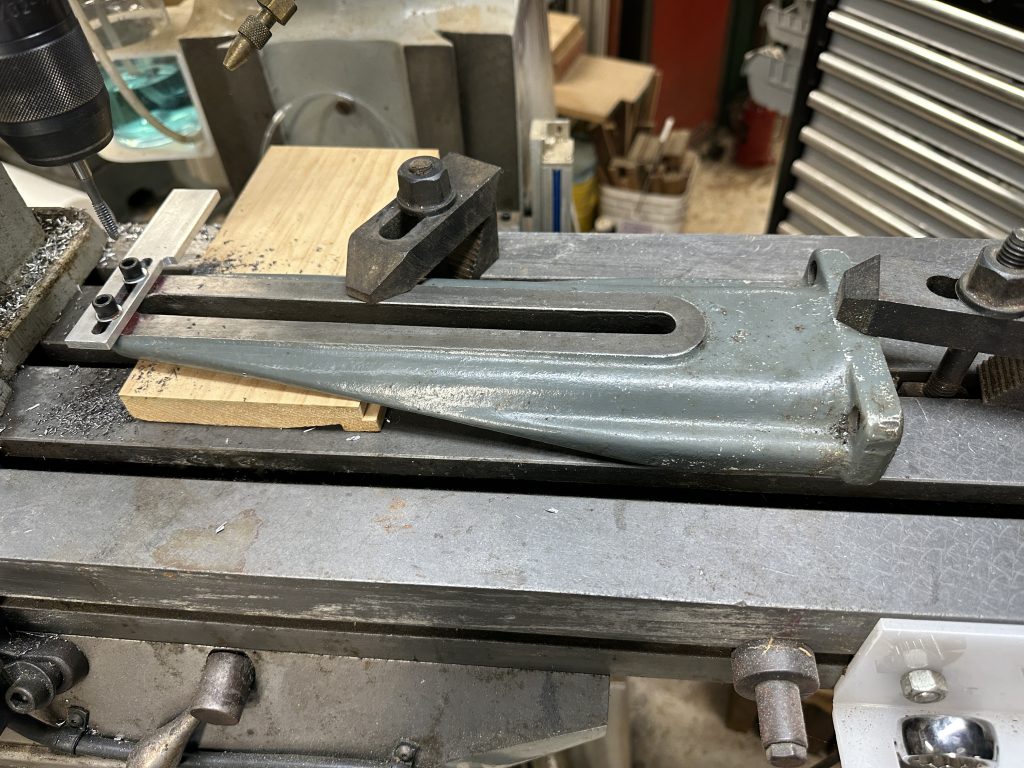
The top mounting piece was made from some 1.5x.25″ 6061 aluminum flat stock. The vertical mounting piece was made from some 0.75×1.5″ 6061 aluminum bar stock. A single screw is used to attach it to the top mounting piece to allow the vertical piece to pivot. Once the mounting blocks were roughly in position, the scale was held in place propped up slightly from the saddle and a transfer punch was used to mark the holes in the mounting blocks. They were then removed, drilled and tapped (M4) to match the hole size on the scale. The scale mounting holes are slotted vertically.
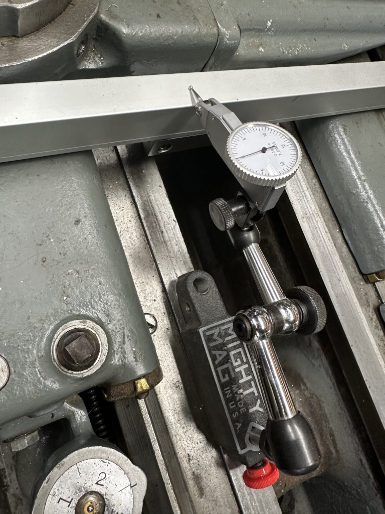
The scale was then mounted in position. The scale must be parallel to the travel of the cross slide both horizontally and vertically within 0.01mm. A dial test indicator was used to get the alignment right. It only took a few passes front to back of the cross slide to have the alignment dialed in.
Now a spacer block needed to be made to fit the existing holes and the scale readout head. There is no way to get a caliper or other measuring device in the gap, so I tested it with drill bits. It turns out a 23/64″ drill bit fit the gap exactly. The mounting block was milled to this thickness and the holes to mount it to the lathe were drilled and counter bored for 5/16″ SHCS (and then opened up a bit for a better fit). It was mounted in place and again a transfer punch was used to mark the holes for the readout head with the shipping shim still left in place between the readout head and the scale. The spacer was taken out again and then drilled and tapped for the M4 screws to mount the readout head. There was just barely enough room to get the SHCS out with a ball end allen wrench without the need to remove the now aligned scale.
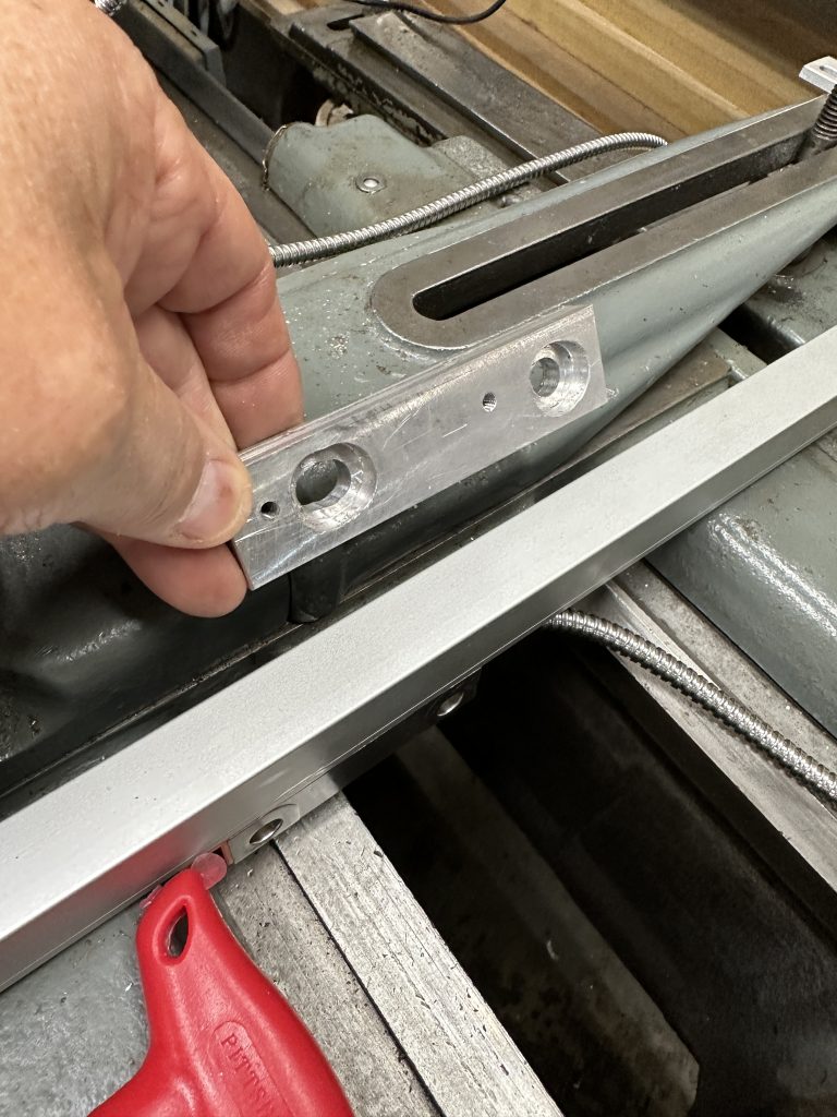
The spacer was installed and the readout head fastened to it. A quick test of the travel still looked good, so I then could remove the shim between the readout head and the scale body. Everything works smoothly and the display reads correctly. The scale is mounted low enough that I still can access the compound rotation locking screws. So, at this point the cross slide scale mounting is complete. Time for a beer.
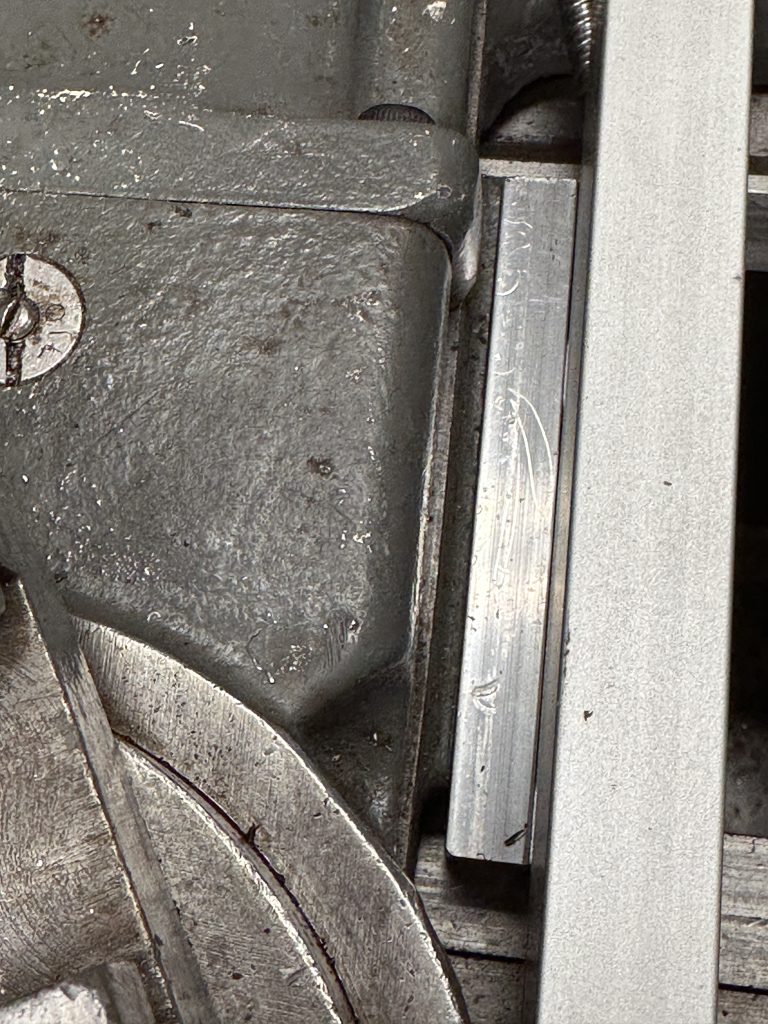
Longitudinal (X) axis scale mounting
The lathe is quite heavy (~1100lbs) and I had precision leveled it to eliminate any twist in the bed. So I did not want to move the lathe. This meant cleaning out behind it and crawling in the limited space there in front of the lumber and paint storage shelves to gain access.
The scale is mounted directly to the lathe bed casting. I was fortunate in that there were no shims required. The scale was positioned and the holes were marked with a transfer punch again. The mounting holes were then drilled and tapped. When the scale was mounted, its vertical alignment was checked relative to the underside of the back of the ways which is a machined surface. I used the blade of a square as a feeler to check the vertical alignment as I could not cover the entire travel with a test indicator as the ends of the scale straddle the lathe saddle on both ends.
I had some mounting angle brackets left over from when I had installed the DRO on the Bridgeport mill. One of these was nearly the perfect size to mount the readout head. The bracket is fastened to the “rear keeper” for the lathe saddle. The keeper is mounted under the back edge of the lathe bed on the saddle. Its purpose is to keep the saddle from rising up off of the lathe bed. It was removed and brought to the mill to drill and tap the holes (1/4-20) for the bracket.

The bracket needed to be cut down in size and the slots lengthened to meet up with the holes in the readout head.
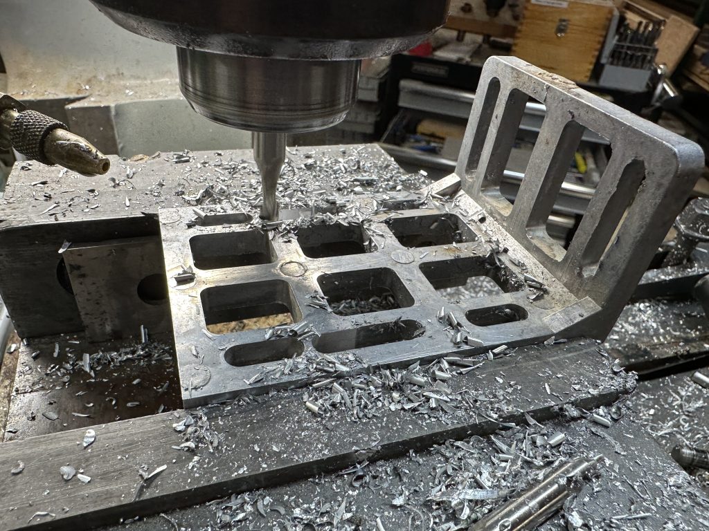
With the keeper and bracket modified it was time to mount them.

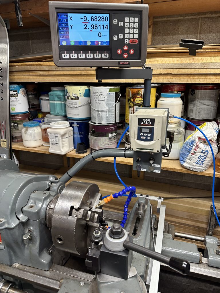
With the scale in place and functioning properly, all that was left was to dress out the cables properly and the DRO is ready for use.
