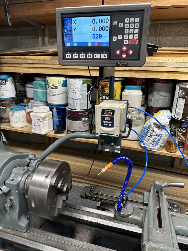
I have wanted a DRO (Digital Read Out) for the lathe since I picked it up and rebuilt it a number of years ago. A session making some metric sized parts pushed me over the edge towards purchasing a DRO.
The unit I chose was Baykunl brand 2 axis with RPM readout and 1uM glass scales. It is available from Amazon: https://amzn.to/3FRxR8E . Note that this is a referral link.
The display arrived nearly a week before the scales. This gave me a chance to get the display mounted above the VFD (Variable Frequency Drive) and controls. The back plate for the VFD mount had just enough room to allow the display mounting bracket to be added. The air solenoid for the KoolMist type sprayer also had to be spaced out to allow the air hose to sneak through the display mounting bracket. The air solenoid is connected to the spare relay output of the VFD and is on when the spindle is turning.
The DRO came with a RPM display and pickup. The pickup is an inductive unit and is triggered by a magnet that is fastened to the spindle. There is a small cover over the end of the spindle and the carriage tumbler gears that looked like it could support the sensor while it was mounted over where the magnet was attached on the spindle bearing take-up nut. It APPEARED that if I mounted the inductive pickup on the rear of the cover that there would be enough clearance. However it was hard to tell and measure the space.

I used the end of the lathe spindle as the reference. The end of the blade of the square is set to the distance to the approximate center of the magnet. This measurement was then transferred to the cover when it was re-mounted in place.

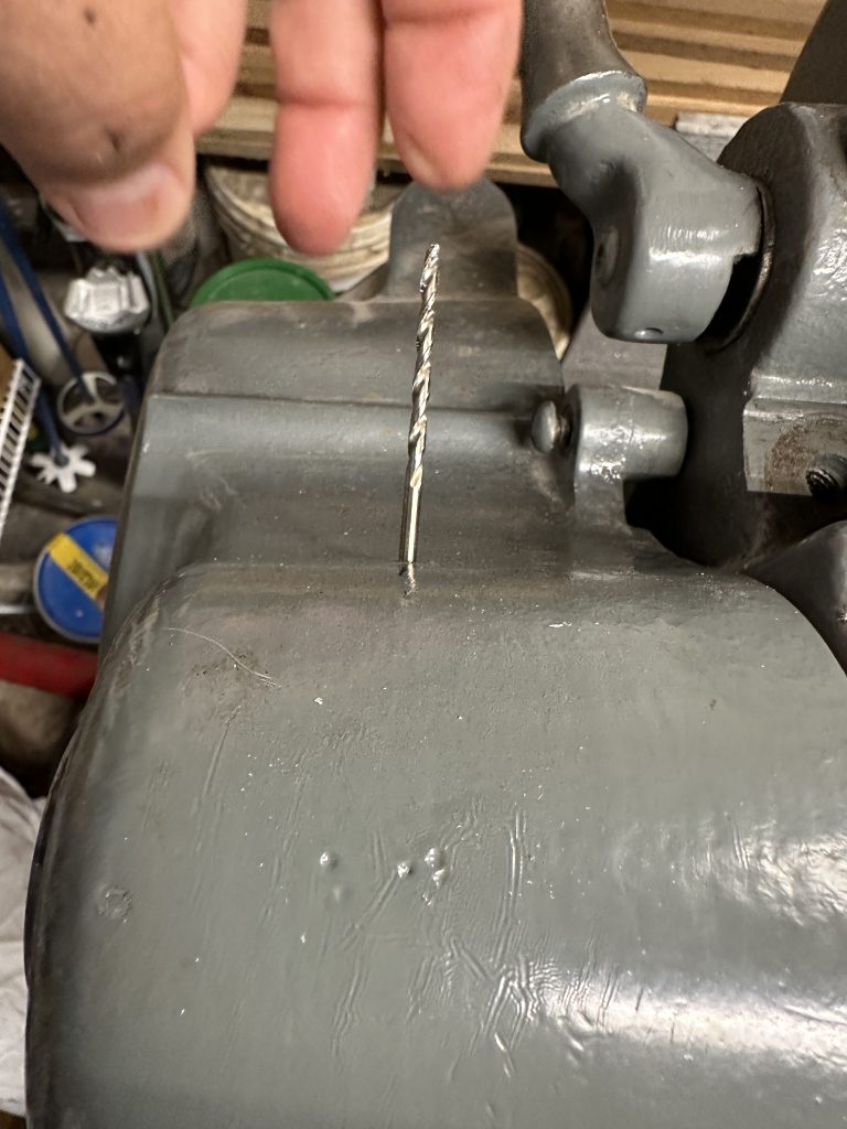
I was still uncertain if there was enough clearance, so I drilled a small hole to check and inserted the drill bit to use as a crude depth gauge.


There was about 1/2″ clearance including the cover thickness. Sp I then drilled the hole to full 12mm diameter and mounted the inductive pickup. I set the depth of the pickup to a minimum to ensure clearance

With the pickup mounted, I put the cover back in place. I turned the spindle by hand to ensure there was clearance and to verify the pickup indicator light was flashing as the magnet went past. The cable was then dressed out of the way.

The RPM readout works nicely and there is the option for 1-5 magnets to be used in the display setup. I am currently using a single magnet, which is secured with a dab of glue to prevent it from migrating from position.

At this point the “easy” stuff is done with the display mounted and RPM readout working. The setup menus on the display are really clear and easy to use. I also like the large color display. I may still lower the display as it seems to be bit high, but I will see how it is in actual use. Now it was time to wait for the scales to arrive as they were shipped separately from China. Unfortunately, when they arrived several days later, they were the wrong ones, with 5uM resolution rather than the 1uM resolution that I had ordered. Since the cross slide scale is reading the radius of the part being turned, the 5uM resolution is not sufficiently accurate (as the readings are multiplied by 2 for the diameter). So now I have wait for a response from the vendor.
