Background
I wanted to see if I could speed up the engraving on my OMTech 130w CO2 laser. The engraving speed is primarily dependent on the X axis drive. The velocity and acceleration of the X axis and the lens head are the main factors to improve without losing steps. As delivered the X axis has a max speed of 500mm/s and max X acceleration of 3000 mm/s/s. My goal was to double these numbers without spending a huge amount of money.
In the common CO2 laser the drives for each axis use 2 phase hybrid stepper motors and drivers. These can provide precise positioning via stepping and micro-stepping as long as you do not drive them too hard / fast. If you push them too fast, then they may “lose steps”. This is seen as irregular cutting or engraving where at a point everything shifts to the left or right, ruining the workpiece(s). So generally, the parameters are set a bit conservatively to avoid losing steps. However, this means that jobs will take longer than they theoretically could with more speed and more power applied. On my 130w machine with most materials, I rarely run >30% power for engraving even when running at max speed. So, it would seem I have room to ramp up the speed and increase the power for engravings. Note that it is possible to set a higher scanning speed in Lightburn than the laser will actually run so up until now I have been stuck at 500mm/s max.
Closed loop steppers provide rotational feedback from the motor to the controller. The idea is that even if the motor “loses steps” the controller will find out and compensate by “adding ” back steps for the motor. So this means that for an equivalent motor and driver the closed loop system can allow higher acceleration, higher max speed and higher jump off speed for filled engraving compared to an open loop system. Note that I mention engraving specifically as at this time, I am just upgrading the X axis. For cutting / line operations, to increase speed noticeably will require upgrading both axis and the Y has MUCH more mass to move with the X axis cross beam included vs the X axis alone. I think that this will be a can of worms to get right and may be difficult with the belt drive used on the laser (vs. the ball screw drives on my CNC router).
Before attempting this level of modification to your system you need to be comfortable with making these changes based on limited documentation and having part to part variation (e.g. simply following a video is not good enough). Making these changes can render your laser inoperable if not done carefully and methodically. Basic troubleshooting skills are required.
Ordering parts and starting
After seeing another post on doing this on Facebook in the OMtech laser group, I took a look at the closed loop stepper drives on Amazon. I was lucky, and there was an open box unit available at ~40% off. So, I jumped on it. Now I had to get the rest of the pieces. A new / additional cable drag chain is needed to be able to easily run the new wires for the stepper motor. You can splice the A and B drive winding wires into the existing wire after cutting out the old motor to avoid running a whole new drive cable for the motor. However, there is also a second cable for the encoder / feedback signals. It is easiest just to pull the new wires into a new drag chain as the existing one is quite full and is NOT an easy open type. On the 130w laser there is just enough space to add a 30mm wide drag chain next to the existing one. Check the space on your machine. You may well need to order a narrower drag chain (even a 15×15 would be plenty big for the 2 cables). Replacing the existing drag chain entails disconnecting all the wires and hose and I do not recommend going that route. Add a new one next to it. The next critical piece is the pulley for the belt on the stepper motor.
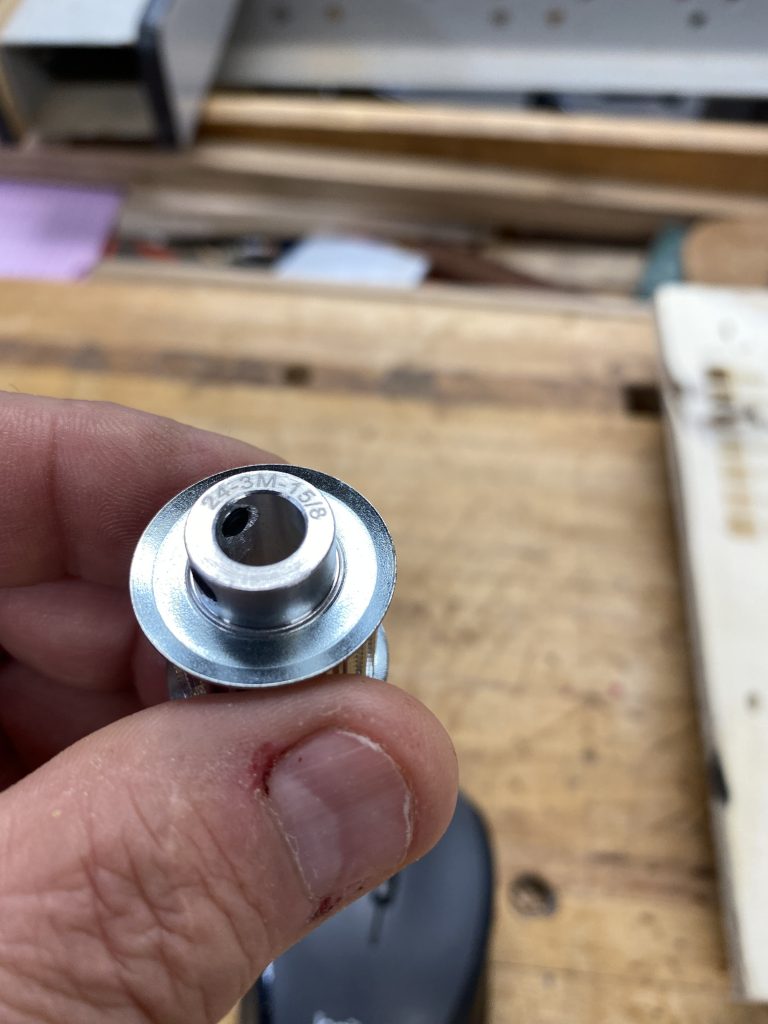
The original poster had a 20 tooth pulley and I blindly ordered it. However, once I started the upgrade, I found mine had a 24 tooth pulley! Not only that but the original pulley was pressed onto the motor shaft so I could not take it off and re-use it. So I strongly recommend unbolting the motor at the “investigation / ordering stage” and counting the number of teeth on YOUR machine. It took another week to get the right pulley. I was able to 3D print a reasonable working pulley to get by in the meantime. However, it was a hassle to find a decent model and then modify it for an 8mm D shaft to fit the stepper. It did “work” but the tooth profile was not great, so I did no push the speed tests until the real metal pulley arrived to avoid damaging the belt.
Figuring out what pulley to order (or make) did take a bit of digging to decipher the labeling scheme:
- HTD toothed belt profile series used in the laser. This is bigger than the GT2 profile commonly used on 3D printers
- 3m – this is the tooth size / spacing, not the company 3M. This is a 3mm pitch (distance between adjacent teeth). Other common sizes are 5m and 8m
- 15mm wide. The belt used on mine is 15mm wide. Actual pulley tooth width may vary and is likely 16-17mm to allow for some degree of misalignment
- 8mm shaft size. This is chosen to match the shaft diameter of the stepper motor
Assembly
To mount the new drag chain, an angle bracket is needed to attach it to the cross rail. I had some aluminum angle that I used. Holes are drilled and tapped in the bracket for M4 screws to attach the drag chain. Similarly the cross rail is drilled and tapped for a single M4 screw to attach it. Lay the drag chain in place and attach it to the cross rail. Now, move the cross rail all the way forward. The drag chain loop size should be similar to the existing one. Next mark the holes for the other end of the drag chain. Note that at least in my case the new drag chain is slightly shorter than than the existing one. If you have a smaller bed you will likely need to remove some links to shorten the chain. This is easier if you remove the snap close tops in that area. Now drill and tap the holes for M4 screws. Be sure to use short screws so as to not interfere with the pass through area.

Temporarily mount the new stepper driver to the right of the Z-axis driver. There is plenty of open space. Again drill and tap M4 holes. Note there are 2 layers of sheet metal. Just drill the top one and be careful when tapping to not go in too far and break the tap or ruin the threads.
Mount the new motor in place of the old one. Cut the cable at least a foot away from the motor so that you have room to work with if you need it as a space for the Y axis later. Alternatively you can pull the cable all the way out, but it is not easy. If you are re-using the existing cable and splicing into it, it is easier if you cut one of the top links out for the drag chain and then pull the cable back to make a loop prior to cutting it. I ran new 4 conductor 18guage wire in the new cable chain for the motor drive. Solder the wires and use heat shrink tubing. Then pull the wires back into the drag chain.

The feedback cable for the motor needs to be pulled into the new drag chain. The new heavier 18 gauge motor drive cable also goes in the new drag chain. The pulley gets mounted on the motor shaft. Push it on nearly all the way, leaving just enough room for one of the locking screws to still hit the flat of the shaft. Tighten both locking screws securely. Mount the new motor in place of the old one. Make sure the front boss of the motor sites in the hole on the cross beam and tighten the mounting screws securely. Make sure the X carriage moves freely and the belt runs true. I was able to tuck the connectors in the end of the cross beam. You will want to add the tie wraps later.
It is now time to connect the new stepper driver to the motor. Note that the connections are in a DIFFERENT ORDER than on the old driver. Take a picture of the wiring on the old driver and write down which color wire goes to each terminal in case you need to go back. I use crimp on ferrules for all of the wires to make neat connections (just like the OMtech factory). Connect the 4 motor drive wires to the new driver (A and B windings). Next connect the feedback cable to the controller paying particular attention to which wire color goes to which terminal. Getting these wrong can damage the motor or driver! The colors to signal pins is listed on the amazon page as well as printed on the motor. Next the controller needs power. On the 130w laser the stepper divers are powered from a separate 36 volt power supply, not the 24 v supply. Connect the +36v and 0v wires to the stepper driver again being very careful to get the polarity right. At this point I unplugged the power connector on the old X-axis driver ( I left it in place for future use for the rotary or as a Y axis spare). Finally disconnect the X axis driver signals at the controller and wire in the new one the same way (step, dir and +5v including a jumper to both +5v terminals).
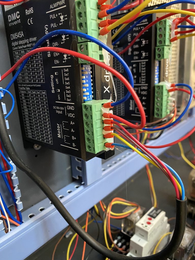
Note that the new motor is longer than the old one

The new driver needs to have the dip switches set for the same number of steps per rotation as the old driver. Look at the dip switches on the old driver and write down the settings in the table on the side of the motor driver. In my machine, it was set for 5000 steps per rotation. Note that yours may be different! Now set the dip switches on the side of the new motor driver for the same number of steps per revolution. Note that you MAY NOT have the same switch settings on the 2 drivers, so look it up in the table on the side of the new driver. If you do not set for the same number of steps per revolution, you WILL have to re-calibrate the X axis sizing, so it is best to just copy the settings and only have to verify that squares are still square.
Now is the moment of truth. Turn on the machine and verify that the X axis homes properly. Y axis will try to home as well, but the motor will likely crash into the back of the cabinet if you let it go as it is longer than the old one. So turn it off as soon as you see the X axis moving. If the X axis is not homing to the right as normal but instead going to the left, the direction needs to be changed. This can be done via a dip switch on the driver (see the notes on the side panel) or you can reverse the wires for the A winding. Power on again after changing and check that the motor goes in the right direction. If the motor did not turn, go back and recheck your wiring from the controller, power supply and and A & B windings . If the X axis is homing, the hard part is done!
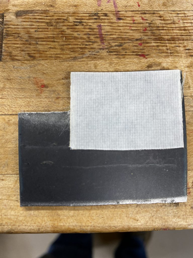
The new closed loop X axis motor is longer than the old one. So much so on mine, that Y axis carriage could not home properly. This can be solved in 2 different ways. 1. Cut an opening for the motor at the back of the laser. 2. Change the Y axis home position and sacrifice a bit of bed coverage On my laser the area to be cut is VERY hard to access and again 2 layers of sheet metal would need to be cut. So I decided to change the Y home position. To change the home position, you can either move the proximity switch (drill and tap new holes) or make a new metal “flag” to trip the switch instead. Given that the switch is nearly inaccessible in my machine (far back right corner under the top cover), I decided to add a metal “flag to the cross beam. The flag dimensions are not critical. I used a piece of scrap steel 1/8″ thick (thinner would work) approximately 3x 4″ and start with 4×4 for testing. I temporarily attached it with double stick tape to test. To test, attach the flag with double stick tape and turn on the laser. It should home normally. If not either the flag is too short (motor still hits the case) or the proximity switch needs to be raised a bit to sense the flag. If it homed correctly, shut off and restart the laser. When it homes the Y axis , turn it off. Now reach in and feel behind the motor for how much space is between it and the rear wall. In my case I measured 2 fingers of space (no way to read a ruler) and then recut the flag shorter so that there would be about 1/4” space between the motor and the rear wall. Once the flag is cut, reinstall and test again and feel the space again. If it is OK, then it is time to drill and tap again to permanently mount it
The flag is permanently mounted on the cross beam with a single screw (drill and tap the cross beam after temporarily moving the X axis sensor out of the way). Prior to removing the sensor, note its height on the cross beam so you can put it back in the same spot. Turn on and recheck the homing for X and Y. Readjust the sensors if necessary. I lost about 1.25″ of Y axis travel with this method. If you decide to enlarge the holes to make room for the motor consider buying or borrowing a power nibbler to do it.

Calibration and Testing
Now the fun begins! Re-burn an existing project file and a square 100x100mm. The project file should be unchanged and the square should be 100mm per side. If the size is off, you need to go back and check the dip switch settings. At this point you could go back to work. However, we want SPEED, so now we need to change the laser manufacturer settings to speed things up. Prior to making any changes, back up / save a new copy of the configuration file in Lightburn.
I have not yet optimized the settings, but have made some starting changes which seem to work.
Configuration changes:
- x Accel was 3000mm/s/s, now 6000 and testing at 8000+ The acceleration will strongly influence how much overshoot there is on raster fills / engraving.
- xMax Spd was 500, now 1000 The Max Speed limits how fast you can request the gantry to travel. This show as a speed up on larger engravings as well as allow you to get the speed high enough to avoid the non-linear low power range of ~10-15%.
- x Jump Off was 40 , now 30 I was getting intermittent stepper driver alarms until I lowered this. Apparently the jerking at the start was not something the driver liked.
Test results
Now save these settings to the laser and re-run your existing tests (previous engraving and the 100mm square). These should both look fine. Now save the configuration in lightburn to the computer (not replacing your earlier backups but in addition),
You could try just increasing some speed parameters in your existing engraving files and burning some jobs. However I wanted to see what the changes did to the burns and how they interacted with the rise / fall times of the laser tube and power supply. It would not be useful to increase speeds if the edges of the engravings got noticeably softer.
I also wanted to see if the scan offset might need adjustment at the higher speeds. I had never had to touch the scan offset table on my machine in the past. The edges seemed to all be nicely aligned in bidirectional fills. Now is when I made a potentially critical mistake. After a successful test the night before, the next day I saw the upgrade notice and I upgraded Lightburn to 1.2.03. Rerunning the old job again showed soft vertical edges even at lower speeds (e.g. 100-200 mm/s)indicative of the scan offset being wrong. Something happened with the upgrade. Also in retrospect, I had been seeing soft vertical edges at 400 and 500mm/s previously but I had blamed, perhaps erroneously, this on laser tube rise/ fall times. Now I had to do a complete set of tests & adjustments to get the scan offset correct at each speed. Unfortunately, I cannot tell at this point, at least for the high speeds, what is due to the lightburn upgrade and what is due to the higher speeds and what may have been a pre-exisiting undiagnosed problem. The process is pure trial & error / iteration. I made a test pattern of 10mm squares with the interval set to 0.5mm. The power levels were chosen to give a “mid grey” burn at each speed. The file could be prettier but it grew organically as I added new speeds after starting with one at 300mm/s.
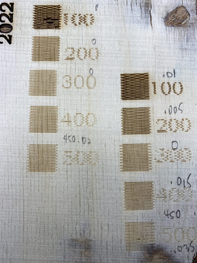
As you can see above, the bidirectional scan lines are not lining up horizontally. I did do a test with unidirectional scan lines (not shown) and they looked good. It helps to document the offset values as you build the table in lightburn. I built out the file increasing the top speed to 1000mm/s and also adding a second line layer to see if the fill and line were aligned and they were. When you use the file, initially turn off the second layer (line) so you can more clearly the ends of the fill lines. The vertical wiggles seen in the 100 & 200 mm/s squares are due to the Y axis stepping. Reducing the “line shift speed” from 20 to 10 improved them but did not eliminate them.


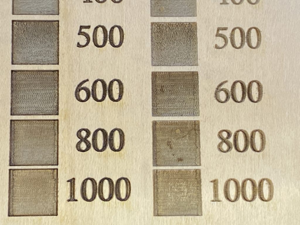

These photos show the ability to increase the engraving / fill scanning by 2x through the use of the closed loop stepper drive.
There remains to be some further work to investigate the slight variations in density at the higher speeds (is it mechanical or electrical?) There is also the vertical wiggle at the slow speeds which may simply be due to using the much larger steps than normal between the scan lines. However by reducing the “line shift speed” , there may be an improvement in vertical resolution – needs more testing to verify.
I think the changes are a mostly a success. However, I was getting intermittent controller alarms which halt X motion at 40mm/s jump off speed. Reducing to 30, as well as send to Ruida and start there so far has seemed to stop the issue (12/21/22). I also added a post covering connecting the alarm signal into the controller to stop the laser when the stepper driver alarms and stops. This is at: https://bronkalla.com/blog/2022/12/22/laser-close-loop-stepper-alarm-interlock/
Parts List
Closed loop stepper motor and driver- Nema 24 3 Nm: https://amzn.to/3VsXkvM
Semi – enclosed 15x30mm drag chain: https://amzn.to/3yJ1BBI
24 tooth 3m 15mm wide HTD pulley for 8 mm shaft: https://www.ebay.com/itm/402047600401
Metric screw / nut assortment: https://amzn.to/3S6jSQa
#30 drill bit: https://amzn.to/3VyP7Gg
M4x0.7 tap: https://amzn.to/3T43LDL
Ratcheting tap handle: https://amzn.to/3gdFA7D or
Ratcheting tap handle with M3-M8 taps : https://amzn.to/3yJdnfc
Crimp ferrule assortment with crimper: https://amzn.to/3Tbb4K3
Assorted colors of 22ga wire
4 conductor 18 gauge speaker wire: https://amzn.to/3Fa44Yd used to extend the motor drive wires
STL models for HTD pulleys: https://www.thingiverse.com/thing:3769619
Referral fees earned on Amazon links.
Files
Scan offset test files created with lightburn 1.2.03
