
I have the OMtech AF3555 130 watt CO2 laser. I wanted to add a rotary axis device that could be shared with my CNC router. After looking around, I chose a 3 jaw chuck style, The unit is a RATTM with 80mm K11 chuck and 6:1 belt drive reduction. If it was only seeing laser use I could have gone with less reduction, but it needs to stand up to the torque of the CNC router as well. The size of the pulley on the chuck shaft is a bit of an issue as I will discuss later. The chuck comes with a separate live center tailstock and 2 sets of jaws (internal and external). It did not come with a connector. These components were mounted some linear rails that I had sitting around for a number of years.
There is the question of: “How to drive the rotary stepper motor?”. There are a few options. It comes down to what is supported by your controller and cost.
- Use the same driver and plug connection as the Y axis. This seems to be the simplest and most common route. However, on my machine it is in the far back right corner of the machine and I have to move it away from the walls to access it. I really dont like moving the machine if I don’t have to. So this is out
- Set up a separate stepper driver connected to the controller as a A or U axis. The Ruida 6445 supports this but according to the Ruida rotary documentation my 6442 does not. See the Ruida rotary doc in the references section at the end. This would be the most elegant route.
- Add a second connector in an accessible location and switch to select the Y axis or Rotary. This is the route I chose
- Add a second connector and a separate dedicated stepper driver for the rotary. This would be a good choice if the stepper motor current rating for rotary is significantly less than that for the Y axis stepper driver and would prevent overheating of the motor. For mine they are reasonably close so I did not go this route.
When wiring up these 2 phase hybrid steppers it is pretty hard to go horribly wrong. There are only 2 windings on the motor. If it spins backwards from what you desire simply reverse the connections on one of the windings. The one really bad thing you can do is connect or disconnect the stepper motor with the power applied. This can result in transient voltage spikes that can destroy the driver. SOME of the stepper driver manuals (such as for the DM542) have nice warnings for this others are just too terse and poorly written. It is a well known issue in the CNC router building community and having destroyed one driver for the CNC router, I am willing to be cautious for the laser as well.
I did not have a copy of the pin-out of the connector in the laser. Also the colors of the wires on the stepper motors and for the laser chassis wiring are not standardized. So the first step was to figure out which motor driver is for the Y and rotary axis. To do this I had the machine off and unplugged the power connection at one the stepper drivers. Then turned it on and waited to see which axis did not home. I hit it on the first try – the middle driver is Y.
Next it was time to power off again and ring out the connections with an ohm meter. The wires on the underside of the chassis connector in the far right back corner are not visible (or I am not a good enough contortionist).

The 4 wires will go through multiple connections and the relay so I started a simple chart in my laser notebook as shown below and worked my way from left to right. Note that yours will likely have different colors – it is the method not the colors noted below that is important.

The Existing Y axis connector pins 1-4 is connected to the stepper driver pins labeled A+, A-, B+, B-. The A’s are one winding and the B’s are the other winding. I also noted the wire colors as they ended at the stepper driver. These will need to be disconnected from the stepper driver and connected to the normally open contacts of the relay. The colors for the added wiring are arbitrary and simply those I had on hand. I did find a source for the crimp on ferules that were used at the factory and recommend that you use them for the added wiring over the stranded wire ends as a nice finishing touch. The wiring is as follows:
- Y axis connector pin 1 , brown wire is connected to the relay socket pin 1
- Y axis connector pin 2 , orange wire is connected to the relay socket pin 2
- Y axis connector pin 3 , black wire is connected to the relay socket pin 3
- Y axis connector pin 4, yellow wire is connected to the relay socket pin 4
Now the common contacts of the relay are wired to the motor driver
- Motor driver A+ is connected to the relay socket pin 9 I used a brown wire
- Motor driver A- is connected to the relay socket pin 10 I used an orange wire
- Motor driver B+ is connected to the relay socket pin 11 I used a black wire
- Motor driver B- is connected to the relay socket pin 12 I used a yellow wire
It would not hurt to test what you have connected so far. With the motor driver circuit connected through the normally closed relay contacts, you have added some connections but really not changed anything electrically. Make sure the dangling relay is not touching anything, plug the Y axis cable back in and power up the laser. It should home and otherwise work just as it did before. If not troubleshoot the wiring before going further.
Drill mounting holes for the 4 pin connector and the switch. The connector does require a big hole (>1/2″) and many will not have a drill bit quite big enough. I recommend drilling the pilot hole (1/8-3/16″) then use the step drill to enlarge the hole. Test fit the male / chassis connector as you go to make sure you do not overshoot and go too big. I also mark the desired ring on the step drill with a sharpie to avoid this problem. I would recommend placing the holes further forward than I did to avoid blocking the side to side pass through (but in my shop I will never use the right side pass through due to space limitations).
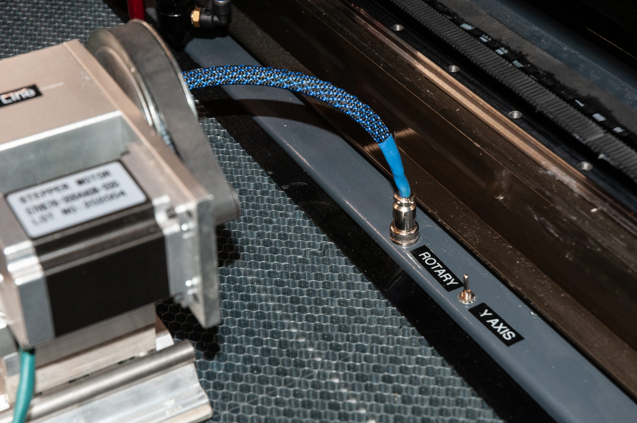
Solder the wires to the connector and leave tails plenty long to reach down to the relay via the cable ducting. Insert the wires through the hole, fish the lock washer and nut up the wires and secure the connector to the chassis. Do the same with the center and one outside contact of the switch. Make sure the outer switch wire faces away from the Rotary connector. This will mean that when the switch is flipped towards the rotary connector it will turn the relay on and power up the rotary connector.
Next comes wiring up the new 4 pin connector
- Rotary connector pin 1 is connected to relay socket pin 5, I used a brown wire
- Rotary connector pin 2 is connected to relay socket pin 6, I used a orange wire
- Rotary connector pin 3 is connected to relay socket pin 7, I used a black wire
- Rotary connector pin 4 is connected to relay socket pin 8, I used a yellow wire
The final wiring steps are to
Get the + 24 v power to the relay pin 14 . I pulled this from the 24 v power distribution block below the controller (red wires). You could go to the power supply directly if desired. It is best to verify that 24VDC is present on the terminal block. The 110VAC distribution block looks basically identical
Connect the center contact to 0v. I pulled this from the 24v power distribution block (black wires).
Place the diode across the relay coil. The cathode (banded end) goes to +24v (pin 14), and the other end goes to pin 13
Connect the other wire from the switch to relay pin 13. Wiring is now complete.
Saw off a 6″ or so section of the DIN mounting rail and screw it down to the bottom of the laser chassis. The relay will clip onto it (some relays you have to hold the catch open when clipping on the rail
Stepper driver configuration and steps per revolution
The stepper drivers have a series of dip switches to configure the stepping / microstepping. The dip switch settings are decoded per the lower chart on the stepper driver. As seen below, on mine the switch positions are SW5 off, sw6 off, sw7 on, sw8 off. Looking this up in the chart, this gives 5000 pulses / steps per revolution. On my laser the steps / pulses per revolution are configured the same for X and Y. However, this is not required and may different on different machines.

The electronic steps per revolution is 5000 and there is the 6:1 belt reduction so the total steps per revolution is 5000*6 = 30,000.
Lightburn and laser controller configuration
To do the switchover from normal Y axis to Rotary axis, it is necessary to reconfigure some of the settings in both LightBurn and the LightBurn Laser machine settings
IF YOU HAVE NOT BACKED UP YOUR MACHINE SETTINGS PREVIOUSLY DO IT NOW!!! It is too easy to accidentally change the wrong item and end up with a non-functional machine. I number and date my backup files. Make a second backup file called “Normal”. This will be used when re-configuring the laser to go back from Rotary to normal X-Y flat operation.
Make sure the switch is flipped to the Y axis setting and power up the laser. It should still home normally. If it does not home, the switch is likely rotated 180 degrees. Turn off, loosen the switch and turn it around (or apply different labeling). Then flip the switch again , turn on and it should home normally.
Configuring LightBurn for Rotary
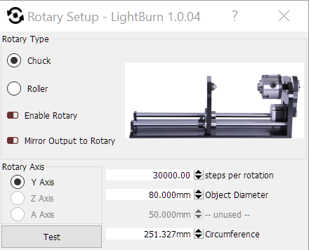
Go to Tools-> Rotary setup
Select Rotary type = Chuck
Select Enable Rotary
Select Rotary Axis = Y axis
Set 30,000 Steps per revolution as calculated earlier
Set Object Diameter = 80 mm This is used to scale the drawing screen to the actual object diameter mounted on the rotary. Use 80mm for now to run the first tests vs the chuck.
Disable “Move from Machine 0” in the Move Menu block. This is needed as there is no “home position” or 0 for the rotary axis
Enable “Start from current position” in the Laser Menu block You will be manually positioning the laser head to start over the rotary mounted object to engrave.

Configuring the Laser Machine settings for Rotary in LightBurn
Go to Edit-> Machine Settings-> vendor settings -> Y Axis settings. and set the Enable homing to False . Otherwise without a home sensor it goes into a weird slow process of trying to home the Y axis and then very slowly moving back and forth for about 2 minutes until you can use the laser. If you forget this , you can wave a wrench a few times over the sensor and it may stop earlier if you catch it in time and time your swipes correctly.
On your way to the vendor settings you will pass the rotary parameters. These apparently duplicate a portion of those in the Rotary Setup above. Changing the settings in one changes them in the other.
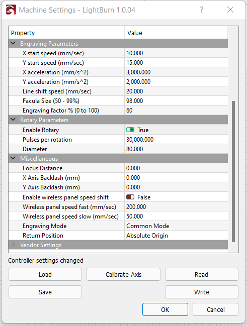

Now write and save the parameters as the “Rotary” file”
Testing
Now is time to test.
Power off, flip the switch for the rotary and power back on. The X axis should home (make sure he carriage will miss the rotary and its big pully).
Manually step the X axis over the chuck. Make a mark on top and align the laser pointer with it. Hit the Rotary setup Test button and the chuck should make 1 complete revolution with the laser hitting the mark on the rotation prior to it returning home.
Next chuck up a test object (small jars work well) that is wrapped in masking tape. Measure the diameter. Enter the diameter in the Rotary setup. Draw a vertical line or skinny rectangle with a height the circumference of the object. Burn that line. It should now meet at then ends (or darn close). If so you are done.
Returning to flat mode
Load the Normal configuration file in the machine settings in LightBurn and write it to the controller. Check that the rotary is now disabled in the Rotary settings.
Turn the machine off
Flip the switch back for Y axis mode and remove the stepper
Power back on and go back to work with normal flat stock.
Parts list
In many cases I bought multi-packs of components as they will come in handy for future projects (such as the time delay circuit for the blower)
16mm Aviation style 4 pin connector and socket (10 pair) https://amzn.to/3tIKgHp
4th axis with 80mm K11 chuck Amazon: https://amzn.to/3nrOSgX
SPDT Switch 10 pack https://amzn.to/3GtA8pq
4PDT relay with socket 5 pack https://amzn.to/33iLAFW
DIN mounting rail for relays https://amzn.to/3GuJykx
1N4004 Diodes 25 pack https://amzn.to/3qrcKmG
3/8″ Braided sleeving for stepper motor wires https://amzn.to/3FGvqn7 Also great to stop your cats from chewing on phone charging cords
Assorted wire ferrules and hex crimper https://amzn.to/3Fv7Lpx This is an Amazingly easy way to make super neat screw terminal connections – just like the factory did. You could get by without and just tin the wire ends
Step drill set https://amzn.to/3rgZZdL These are handy for holes in sheet metal. Equivalent step drills can be found at Harbor Freight as well
Commissions hopefully earned on Amazon links.