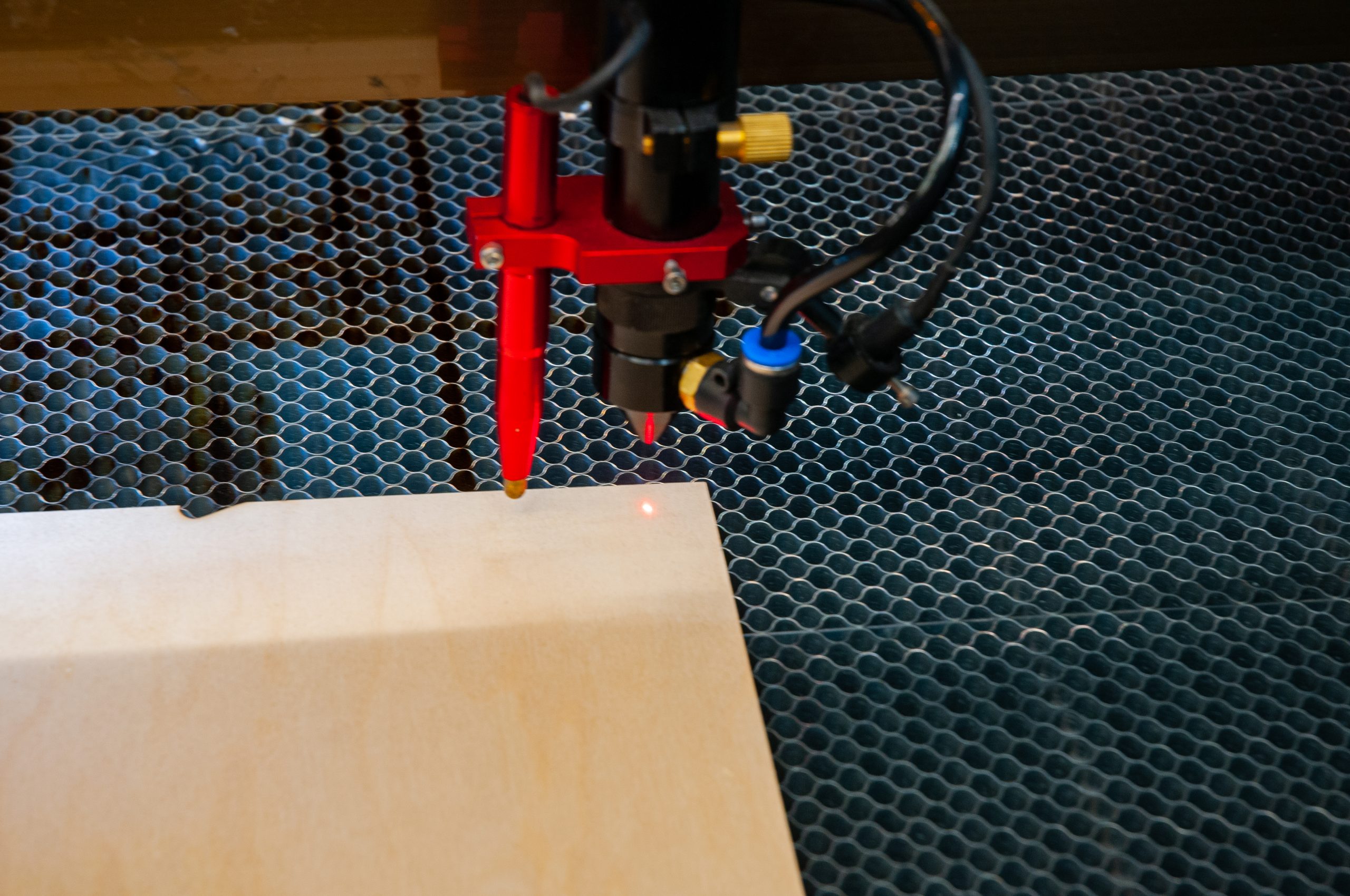
Having a “red dot” pointer is a nice accessory for a C02 laser. It provides an easy way to align the head indication to the material, do “framing runs” to highlight where you hope your design will land on the material, etc. However, the external / angled laser red dot devices leave much to be desired:
- They are generally mounted on the nozzle tube. This means that there is one more thing to take off, re-apply and adjust every time you clean the lens or switch lenses.
- The laser pointer can interfere with homing either the X or Y axis. If the pointer laser is out of position (angled up or twisted) it can hit the guide rails for the laser head.
- The laser pointer is only “accurate” at the proper focal distance for the laser lens once it is aligned. The pointer is angled in from the side and if the height of the work piece is high or low from where the pointer was adjusted the alignment will not be accurate.
- The laser pointer “dot” is a rather large ellipse due to the angle that it is aimed from, as well as the cheap lens in it.

In order to alleviate these issues / annoyances, I decided early on to use a laser beam combiner and have the pointer red dot follow the same line path as the C02 laser beam. I ordered the beam combiner at the same time I ordered the laser machine. However, I did not realize that there was not a good way to mount the combined mirror 1 and beam combiner assembly in my laser. The laser machine is an OMtech, AF3555 130W unit. The problem is there is very little physical access at the mirror 1 location and the base would have to be shifted, due to the post not being directly under the mirror in the combination unit but rather centered between the mirror 1 and the beam combiner (partially reflective mirror). I did no like the idea of having to drill holes near the laser tube or having to remove it and the base the mirror and tube are on is “blind” with no access underneath.
This meant I would need to move the location of the beam combiner to between mirror 1 and mirror 2. There is just enough room to the back of the machine, behind the Y axis home location. The flat area it would need to mount to is significantly lower than the area under the mirror 1 mount and tube. The provided shaft for the beam combiner assembly is not tall enough. I roughed in the height needed with a piece of paper attached to the beam combiner and made test pulses.
Beam combiner mounting block
This meant I needed to “block up” the base of the beam combiner. I chose 1/2″ acrylic so that the laser could once again make some of its own parts. At this point, I did not have an accurate location of where the beam would pass through from side to side. So I made multiple mounting holes for the beam combiner base to allow for adjustment in addition to the slots in the base.
I used M5 screws for both mounting the block to the laser and the beam combiner base to the block. The holes were drilled 4mm and then tapped. For the laser cut tapped holes, I drew them slightly undersize to allow for the beam kerf. When tapping in plastic it is very easy to get the tap jammed due to the chips heating up while cutting, lodging in the flutes of the tap and then setting up hard. Use wax or oil as a lubricant. Proceed to tap part way and back the tap out and restart several times on each hole. I then mounted the beam combiner to the block and set it in position at something close to the proper height and angle and then made some more test pulses on tape. It quickly became evident that to adjust the darn thing I needed to be able to get 2 or 3 hands in at the same time as the shaft would drop down into the base when trying to turn it. On top of it, realistically I could only manage one hand at a time in the tight space provided. I could not simultaneously reach in from the side and over the top and in from the working area.
When mounting the block to the laser, get one of the corner mounting holes drilled and fastened down. Then you can use the block as a drill guide for the remaining hole(s). In the blind corner it is very difficult to measure and mark for holes. You only need 2 or 3, not all 6 screws, but I figured it was easier to cut too many holes in the plastic and then have choices rather than too few.

Beam combiner height collar
In order to be able to angle / pivot the beam combiner without it constantly slipping down into its base I needed to make a locking collar that would mount to the support rod and then ride on the base. The dimensions are not critical other than the 10mm hole for the shaft. I had some aluminum rod stock available and used it. I faced and turned it on the lathe then drilled the shaft hole while still in the lathe chuck. The piece was then parted off, re-mounted in the chuck and faced off again. So now the top and bottom are flat and close to parallel. I drilled and tapped two M3 holes approx 90 degrees apart in the sides. M3 Socket Head Cap screws were used to lock the collar on the shaft. It is now relatively easy to set and lock the height while allowing the assembly to turn to get the correct angle for the beam combiner. You could make the collar out of acrylic or other materials as well. Another option might be to try a collet style drill depth stop or a shaft collar.
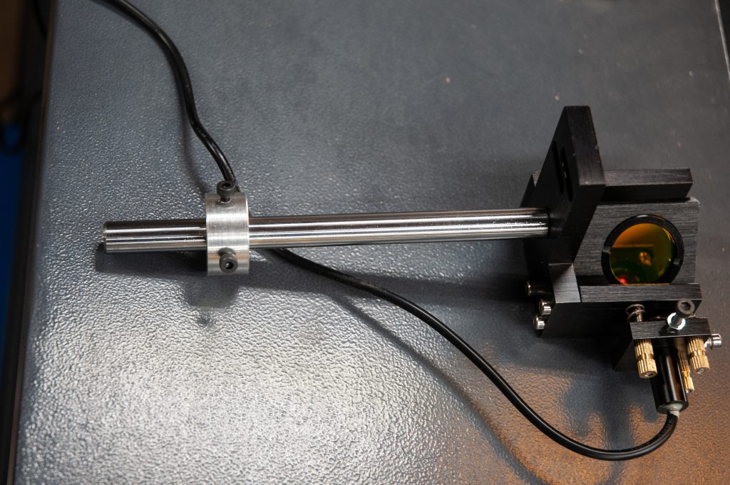
Laser Pointer
The laser pointer provided is a sloppy / loose fit in its mounting block. It has 1 screw to clamp it and can still wiggle. As you might guess, this movement throws the pointer beam way out of whack. I drilled and tapped the mounting block for a second M3 screw. Then I wrapped some aluminum foil tape around the pointer to minimize the gap. It seems to hold reasonably well. If it gets troublesome I will either add some solid brass shim stock or make a new mounting block.
The laser pointer needs a 5V power supply. I ran the wires to the other side of the machine and tapped into the same 5V power that runs the old laser pointer. The laser pointer comes with a female DC power socket. I had some male ones in my parts bin and used one for the connection. This makes it easy to take the entire assembly out if needed (as I did to flip the beam combiner mirror).

Beam Combiner Orientation
The beam combiner disk appears the same from both sides but it has a partial mirror surface on one. This needs to be facing the laser pointer side. There was an arrow / V mark on the edge but no explanation of which way it should face. So it was trial and error. It turns out that once you see the reflected pointer beam and compare it on both orientations of the beam combiner it becomes obvious, which one is right. There is a nice Youtube video from American Photonics on this.

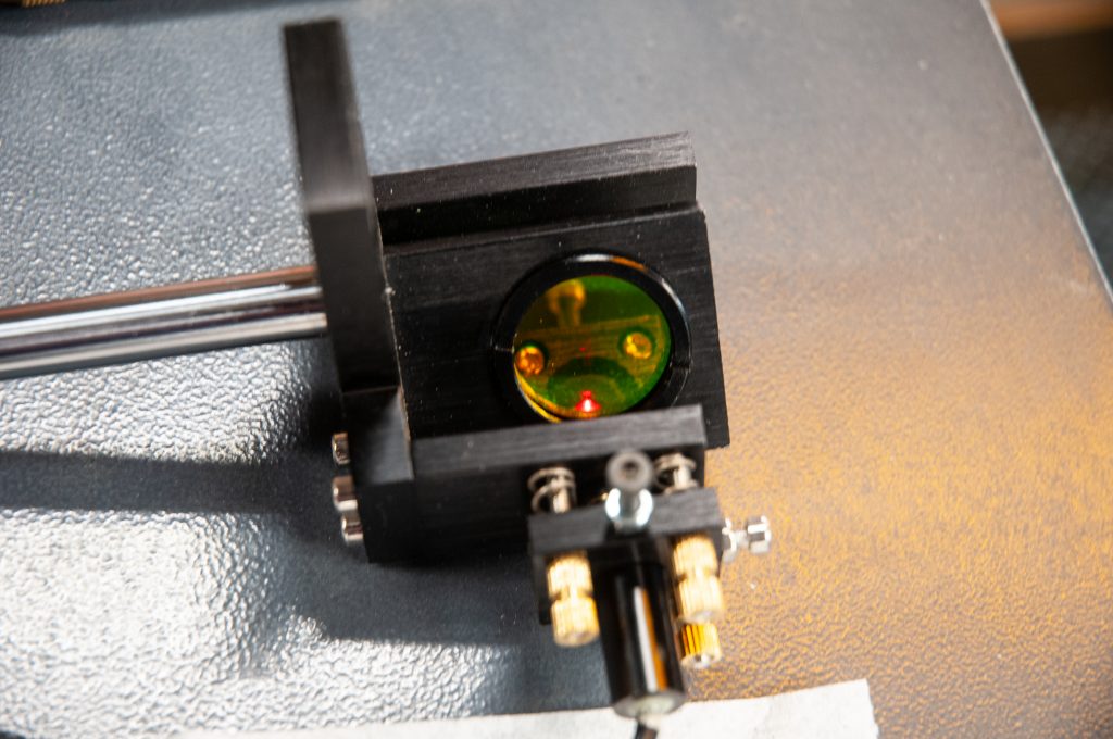
Final installation and alignment


I already had my laser properly aligned. Adding the beam combiner added a tiny shift to the beam. I did re-tweak mirror 2 to compensate for this (or I may just be getting more picky over time). The same methods are then used for the beam combiner.
1 Place masking tape over the laser tube side of the beam combiner frame. Adjust the height of the assembly first to line up the pointer spot with the mark on the tape on the combiner. This is critical as if the height is not right you cant get it to track to mirror 2&3 as they move


2 Next, clean the beam combiner. Then rough in the sideways angular alignment by getting the pointer dot to hit the tape burn dot on mirror2.

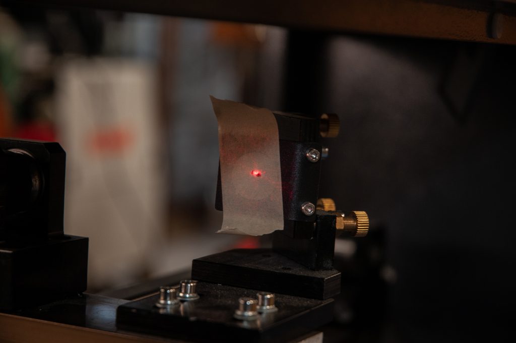
3. Tighten down the base screws for the support for the beam combiner. Now fine tune the left right alignment using the screws on the pointer holder to make sure it hits the tape burn mark on mirror 2 near and far. DO NOT touch any of the mirror settings.
4. Go for spot alignment at mirror 3 hitting the tape burn dot, using the screws on the bracket holding the red dot laser .

5. The final check is pulsing and burning a spot on the wood below the nozzle and seeing the smoke light up and the 2 dots are centered, – red dot on top of the burn spot.
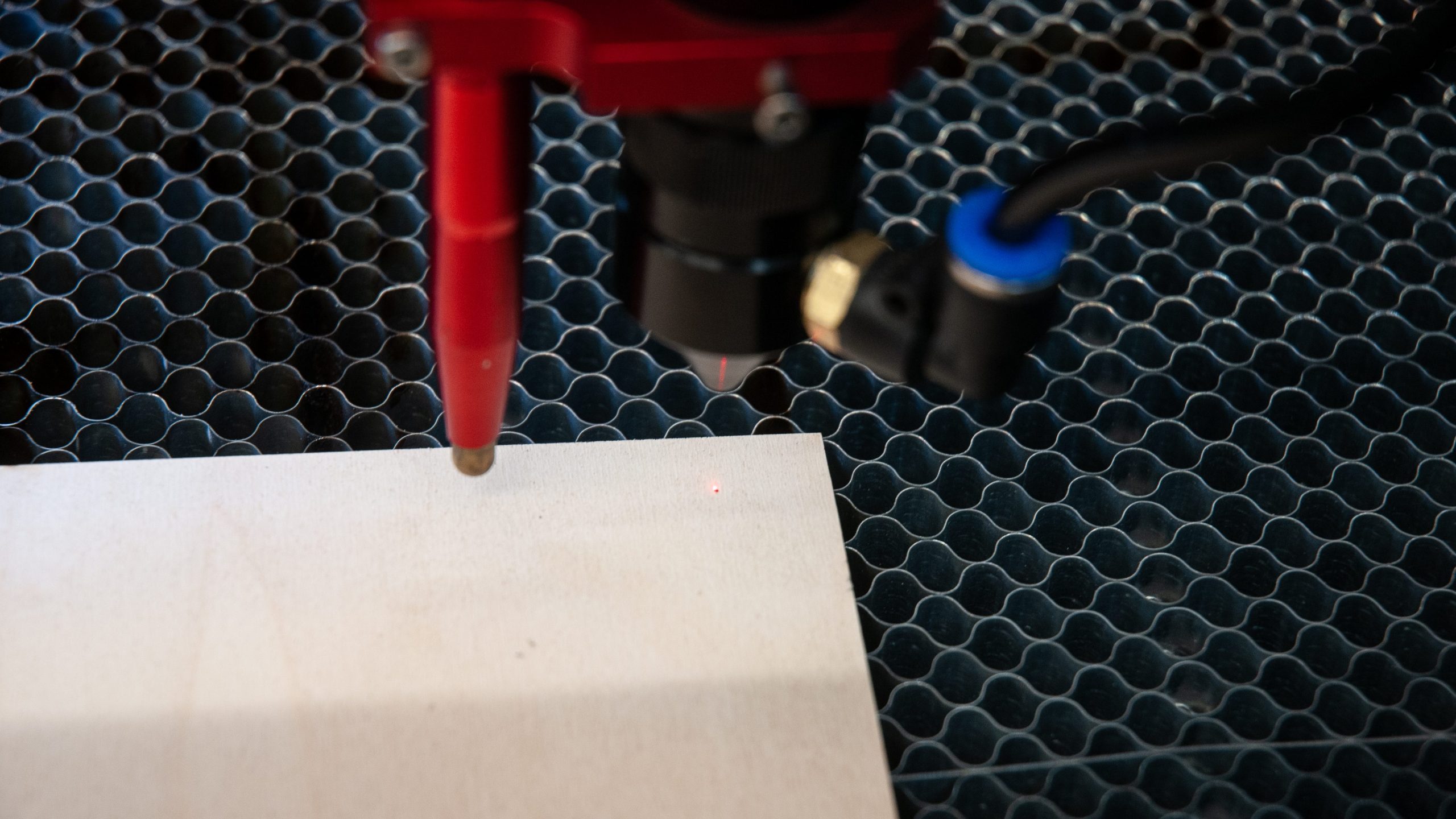

Now clean the beam combiner as the tape was very close when the laser was pulsed. It accumulates a LOT more smoke than the mirrors where the tape is on a frame a short distance away. Re-tweak the alignment at mirror 3 with another piece of tape and I was done. Remember, the red dot is not a reference for mirror alignment of the CO2 laser beam but rather it is set up to follow the path of the CO2 laser beam. Before using it for a stitched / cut & print, double check the red dot to pulse burn alignment and tweak to be as close as possible (requires 2 people on my machine when the laser head is in the front right corner). Note that it is not quite as bright as the original angled red dot pointer.
Now I have a high accuracy red dot for alignment of the work. I removed the original red dot and installed a DC power connector, the same as for the one on the beam combiner in case it is ever needed again (or to use as a spare for the pointer for the beam combiner).

Parts:
Choose a beam combiner assembly that matches the mirror diameter of your laser. DO NOT go smaller for the beam combiner or you will lose power and possibly damage the beam combiner.
Cloudray – combination mirror 1 and beam combiner E series set B with mirror and beam combiner https://www.ebay.com/itm/123589673559 or https://www.cloudraylaser.com/products/cloudray-e-series-1st-mirror-mount-with-beam-combiner?variant=39660365021345 Note this is the one that I ordered that did not fit. I removed the mirror and its mount and now have a spare. Note this is a 25mm diameter beam combiner and mirror
Cloutdray beam combiner: https://www.cloudraylaser.com/collections/co2-laser/products/cloudray-znse-laser-beam-combiner-set-style-b This appears to be a 25 mm beam combiner if you click on the right thumbnail SKU: MP09LCBCS25S
DC power plug 5.5×2.1mm with screw terminals https://amzn.to/3zQJ8lM
