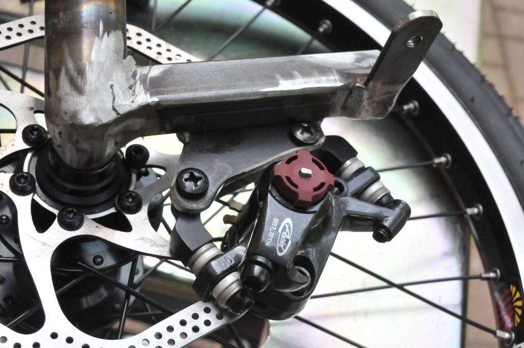
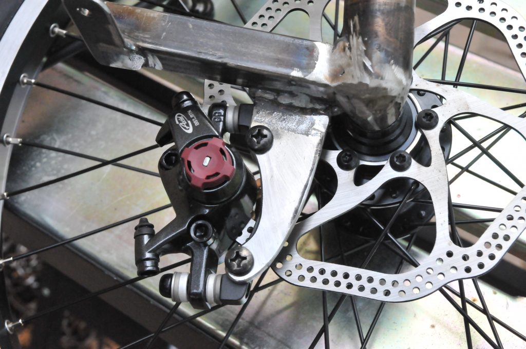
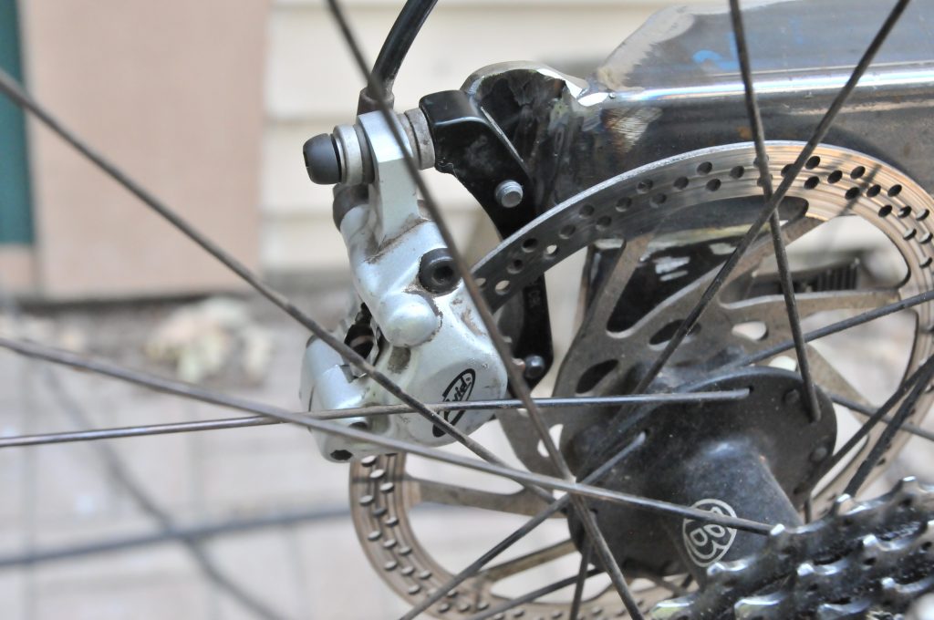
The trike is set up with disk brakes. The fronts are new Avid BB7 mechanical and the rear is a used Avid Juicy 5 hydraulic. All have 160mm rotors.
Mounting the brake assemblies requires fabricating some odd shaped pieces of steel to weld to the front wheel assembly and the rear fork. The easiest way to do this is to make templates from paperboard. First the template is attached to the brake assembly and successively trimmed while fitting the brake on the rotor. Make sure that the brake is out far enough so it does not rub on the peaks of the non-round rotors.
For the mechanical brakes you can adjust the pads to hold it in place, however this is sensitive to slightest movement of the bike. The mounting plates were cut from 3/6″ steel flat stock. My bandsaw has a 1/2 ” blade so the curves to a number of passes and a lot of grinding. The grinding was done on the bench grinder, some 1.5″ sanding drums and the combination belt / disk sander. The mounting holes are 6mm diameter.
Once the shape appears close, then more test fitting is done (and more grinding). The plate is then clamped in the correct alignment with a small c-clamp. The clamp is important as otherwise it is too hard to hold at the right position to get good solid tack welds. Then the plate gets tack welded in place. Now spin the wheel and actuate the brake. It should spin nicely and stop nearly instantly with hand pressure on the brake actuator arm. At this point, the wheel and brake are removed to complete the welds. You don’t want to damage the brake with excess heat, weld splatter the rotors or tires. In the end the Philips screws will be replaced with socket head cap screws and properly torqued. These were just easy for testing and not tearing out of the paperboard templates
This is done for each of the brakes. The mounting will vary for each wheel although I was able to reuse and trim one of the front templates for the rear. Note that the rear brake is mounted behind the fork, not under it as the plans show
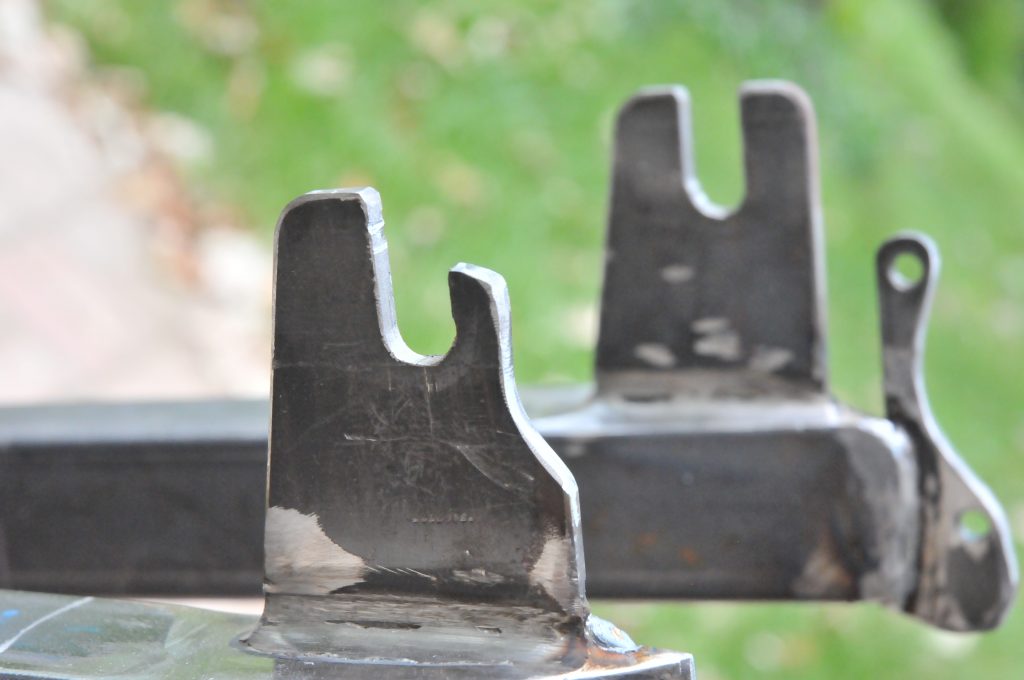
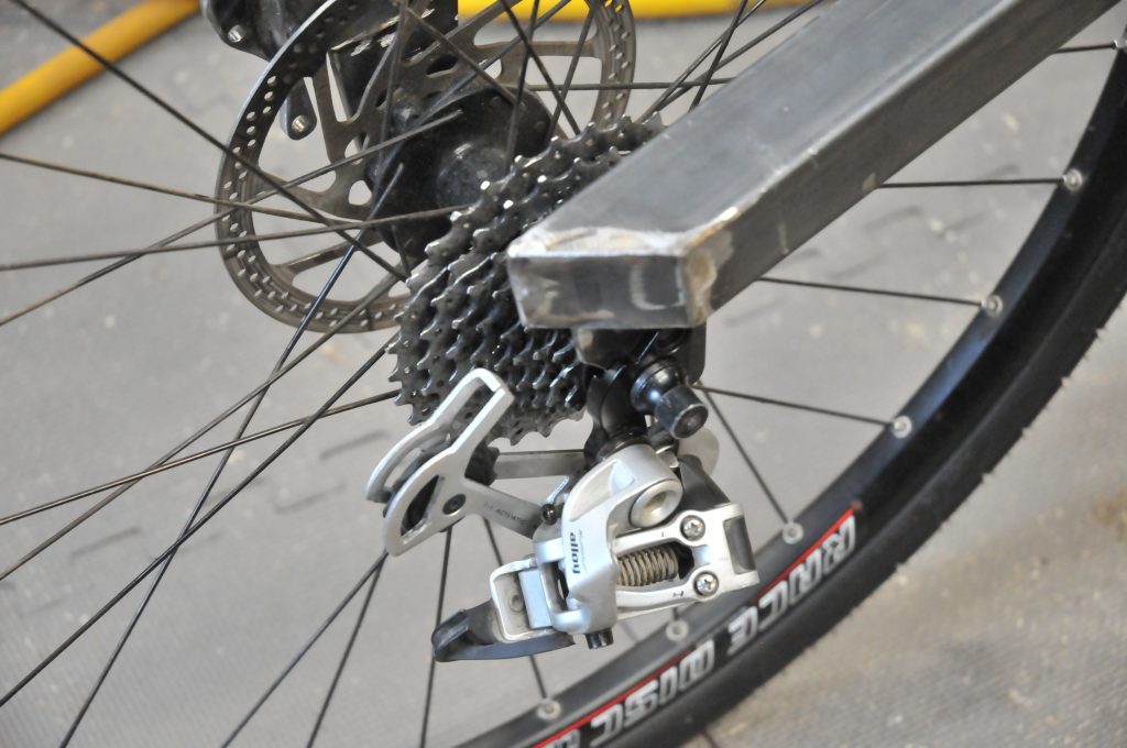
The next step was to modify the rear drop-out to fit the rear derailleur. The derailleur is a used long cage SRAM X-9. This involved quite a bit of grinding to fit the recess in the derailleur for the original bike drop-out. Comparing to the other side, you can see how much had to be removed. In the background, you can also see the profile of the rear brake mounting bracket. I still need to drill a hole and make a new bushing for the retaining bolt for the derailleur. (there is probably a more proper term for this, but I don’t know it). At this point it would fall off each time I remove the wheel. The derailleur travel still covers all of the sprockets when moved by hand.
The seat needs to have mounting tabs to secure it to the frame. These are about 3″ long and I had the ends drilled with a 5/16″ hole. The brackets are welded to the frame and ground flush. The seat is placed on the completed brackets and the holes marked. The were then drilled for 1/4-20 T-nuts which are mounted from the top. This makes for a very secure mount.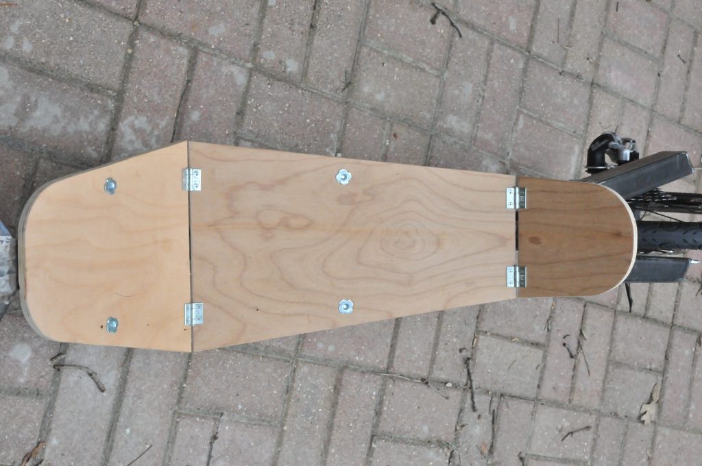
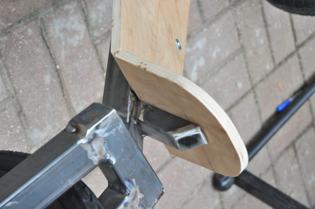
Once the seat is mounted then a small “backrest” bracket must be made form 1″ tubing and fitted. This an be seen below. I had test fitted it, in the process of setting he angles and after tacking, but it seems a bit steep right now. It may be cut and adjusted after the padding is on the seat.
 In addition to these items I did a fair bit of weld grinding and clean up today as well. Overall, it was a productive day.
