
The table top is the largest part of the project. Not necessarily the most complex but certainly the most time consuming. As a result, I ended up working on multiple other items, notably the table top support structure, in between. For example. after glueing up the top , I was working on the slider rail components. So, the following article while focussed on the top and its joinery was only a portion of what was worked on in the last couple of weeks. However, I have gathered the work sessions together to provide a more coherent story of working the top and will do so similarly for the under framing.
Because the top is for an extension table, the top is made up of pieces of wood that run across the width of the table. This is done so that the seasonal expansion and contraction of the wood will not affect the alignment of the joints too much. As I am building the table it is February in Wisconsin. With outside temperatures now in the -20 to +30F range, the humidity is reaching the seasonal bottom. So I have to be careful to ensure that the wood movement will be accomodated and it will be mostly expansion from here on out.
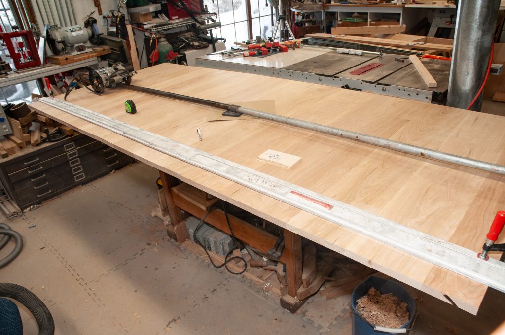
The initial glue up of the 3 slabs is fairly straight forward. The top, including the center wing is to be 8 feet long and about 41″ wide. The center is approximately 24″ wide and each of the end wings is ~36″ wide. The pieces were jointed both by machine and with hand plane tuning of the joints. They were then glued up. At this point the joints in each slab were then hand planed and scraped to be reasonably flat. With the faces reasonably flat, it was time to attack the edges and square up the pieces. My stock was not defect free and I started with glue-ups that were about 46″ across with the hope of 40-42″ clear center sections. The defects at the ends included knots, tear out and jointer snipe.
Squaring the panels
The first step was to rip the panel pieces to width so that both of the long grain edges were parallel. The next steps were to cross cut the pieces to the approximate width of the table top so that they were then neat rectangles. I did this by using a large drywall square clamped to the top and a circular saw for the first pass and then a second pass with a router and 1/2″ end mill to clean up the cut. The router pass took off <1/8″ and left a nice clean finish (without any saw marks / burns). The goal was to get the pieces within 1/8-1/4″ of final width when they were all lined up.
Making the butterfly wing
The center panel then had to be cut in half across the width of the table. This was done on the table saw. The edges for the center joint were then tuned up with a hand plane to remove any saw marks. The butterfly wing uses Soss brand invisible hinges for the center joint. These allow the wing to fold back on itself 180 degrees and are invisible when the center wing is opened flat. The hinges need to be mortised into the center edges of the butterfly wing panels. The alignment is critical, so I used a micrometer adjustable fence on the router to set the distance of the mortise form the table top and then carefully marked the ends of the 2 sets of mortise cuts. As you can see, the green masking tape is used to help make the ends of the cuts more visible. A plunge router with 1/2″ carbide end mill (up cut spiral in router bit terms) is used for the cuts. The longer cut for the lip of the hinge is done first which is ~1/4″ deep. Then the plunge depth is reset for rest of the hinge mechanism mortise (~7/8″ deep) and the narrower deep mortise is cut in 2 passes. I made the cut for the lip purposely a bit deep to allow for final planing if required and adjustment of the fit, shimming up the hinge ends with plastic card stock (hotel room key cards).

I had a recessed pull left over from the boat construction and it adds a nice touch to the leaf, making it easier to grasp the leaf to open it. The placement is such that the pull handle will lay on top of the outer rails so that it will not hang down when it is open.


I also tested the operation of the butterfly leaf in the table frame. The goal was to ensure the leaf really fit prior to putting in the alignment pins and setting the final width of the table top. Construction of the frame will be covered in a future post.
Alignment pins and final trimming
Pins are used to align the leaves of the top. This is to counter some warping and keep the butterfly leaf level with the rest of the top. Having matched sets of holes was a bit of a worry bout I found a doweling jig at Rockler that is just the thing for this. The pins and their sockets require 8mm / 5/16″ holes in the edges of the top panels. The holes for the two large end panels are drilled first. Then the butterfly leaf is drilled to match the corresponding mating side holes. A 5/16″ drill bit in the large leaf hole accurately aligns the jig for the butterfly leaf holes.

Now the pins and sockets could be placed in the holes for the test fitting. Everything fit perfectly. However the 5/16″ holes are a tiny bit large for the 8mm hardware. Getting the pins out was easy. However the sockets are not easy to grasp> I sacrificed a small screwdriver to the cause. I heated the tip red hot with a torch and bent it at a right angle. This took a couple of passes. Then I cooled it by plunging into a block of wax, rehardening it a bit. The pins were then glued in with thick superglue. The sockets were set about 1/32″ below the surface to allow for final tuning of the joint.

Next the long edges of the top had to be trimmed to final width. The ends panels were about 1/4″ wider than the butterfly leaf. The final trimming was done with a router and 1/2″ end mill. I made an alignment jig by routing a scrap of plywood to the width of the router base edge to the edge of the bit. This was used to set the long straight edge (Rip Straight) and it was clamped in place. 2 passes were made – one at 1/2 depth and one at full to allow fast enough of a cut and eliminate burning.


The top was scraped and then sanded as one large panel. Sanding was done with a random orbit sander at 150 and then 220 grit. Final sanding was by hand with a sanding block in the direction of the grain

The edges were then partially rounded over with a 5/16″ round over bit. This was not a full depth cut but instead left a bull nose profile. As you might expect there was some tear out of the end grain. The video below shows how to clean this up.
The top is now ready for finishing. However, with subzero temperatures this will have to wait a few days (need ventilation). So on to cleaning up the frame and rail system.