The path light side panels are built separately from the roof. Once they are complete they are soldered to the roof. The bottom is the final piece that is added.
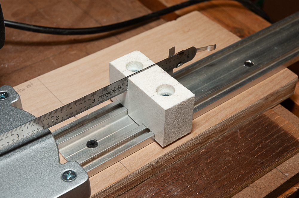
The side panels are built from pieces of adjustable brass came and brass U came that are soldered together. The thin brass is most easily cut with a small 2″ cutoff saw (Harbor Freight). To smiplify the setup and aid repeatability I added a small aluminum track (left over garage door bottom gasket) and an adjustable stop (expanded PVC) which has a slot to hold a small 6″ pocket rule for measuring the distance from the blade. There are no dimensions provided as this is a “make it to fit” from scrap sort of thing.
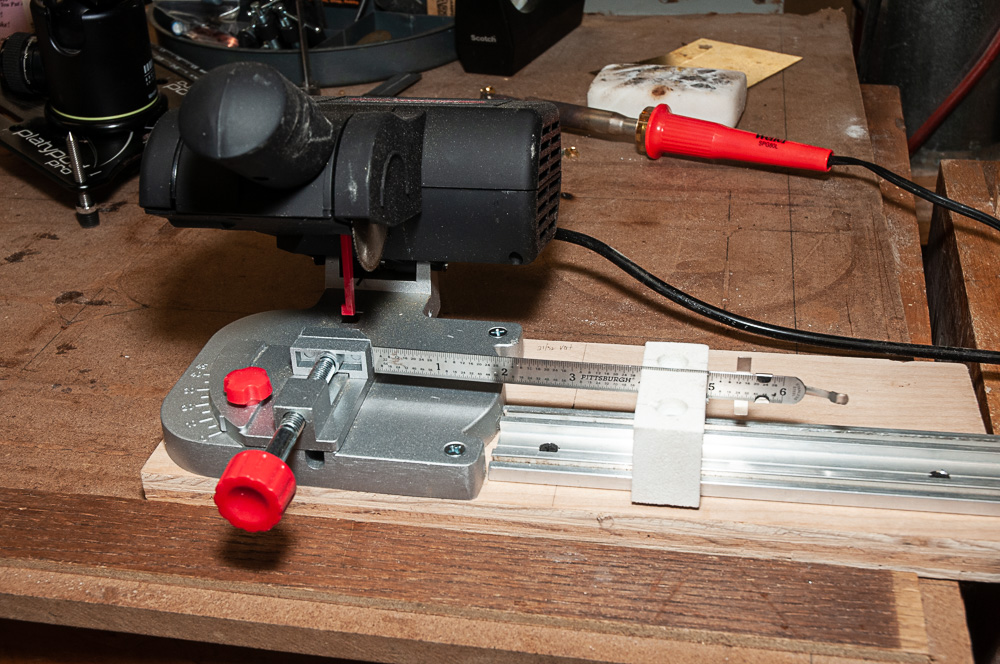
The cuts for the track were done on the table saw. Just datoes that were adjusted until the stop block fit. The 8-32 screws fit into nuts that are held in the track. The track opening had to be opened slightly (0.010″) by running it over the table saw. Setting the gap is SO very handy with the rule held in place. The slot was cut with Japanese style pull saw. It is just a friction fit for the rule in the slot
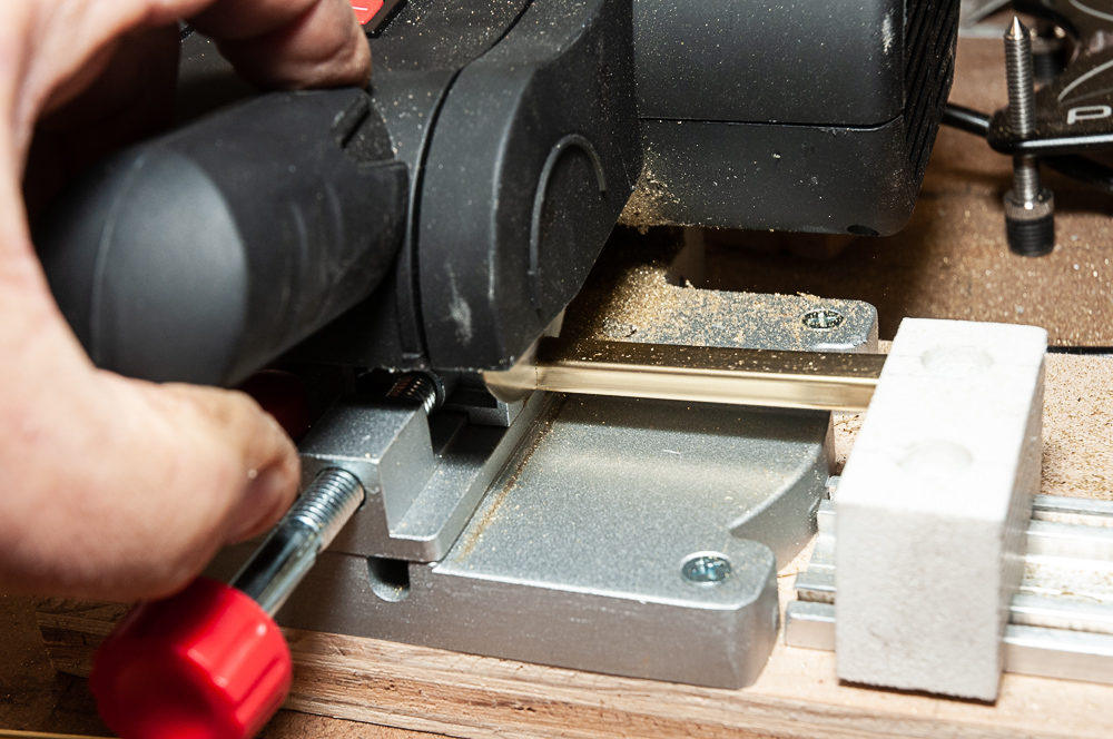
Cutting is easily 5-10x faster than having to measure , mark, set the piece and then cut. Just move it to the stop. It is also much more accurate and repeatable as well. Cutting through the adjustable U channel, it wanted to bind on the blade. Waxing the blade helps tremendously. I use Lenox blade lube (same as for my metal cutting bandsaw) but beeswax, paraffin or SnoSeal would work as well. It also helps to support the cut off piece with your fingers (although it renders photography useless) and prevents some end damage and the part being flung as it is parted off.
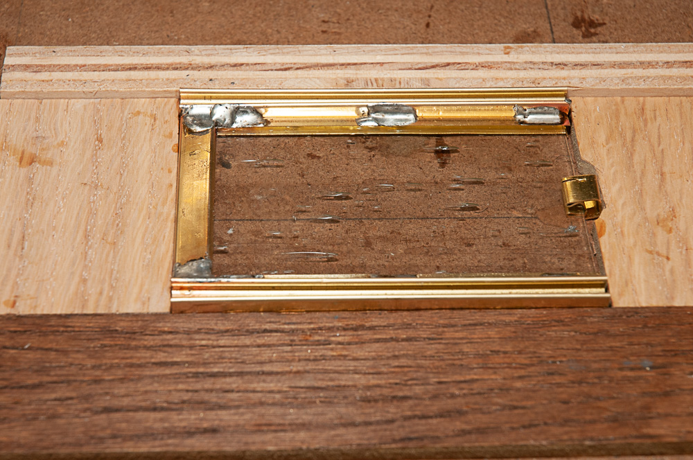
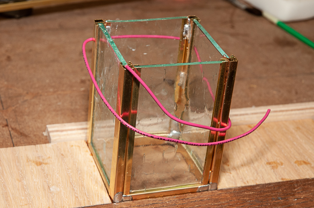
The glass is fitted in place prior to soldering as this helps greatly with keeping things square and the grooves aligned. Thin plywood pieces make up the fixturing. A scrap of the adjustable U came supports the glass at the bottom. The pieces are soldered together with dabs / tacks. There is no need to run the solder the full length of the corners.
Once a pair of these side panels have been assembled, the other top bars for the front and back are soldered in. Light wrap of wire helps keep everything together and upright while soldering. Alternatively a square or even the block of sal ammoniac can be used to brace the pieces.
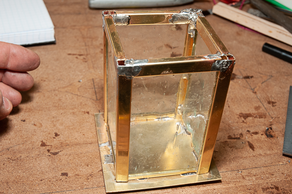
Once the sides are completed, the bottom panel and U channel is added. There are 4 corner holes and a 29/64″ hole in the center for the light socket. #8×5/8″ stainless screws fit the adjustable U channel to hold the brass base plate on. Initially I used the soldering iron to solder the u channels to the base, but found that using the microtorch to heat the base and thereby heat the U channel was much easier and neater. The downside is if the movement of the torch is paused, the glass will crack. I lost 2 out of 32 panels this way. As you will see in the video the indirect heating approach is much neater.
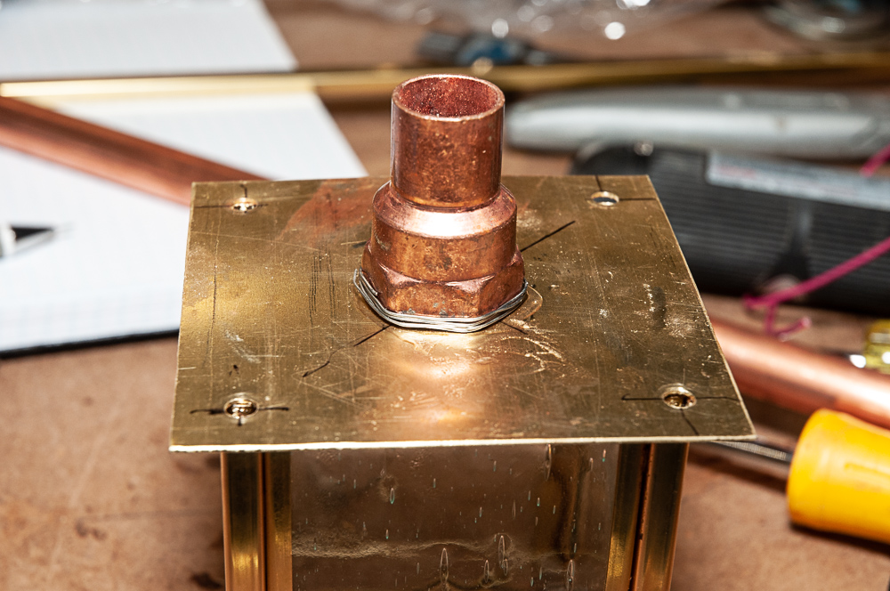
The support for the light is a 1/2″ copper pipe to 1/2″ threaded pipe adapter. It provides enough support and is easy to solder in place. Once cleaned up and coated, it actually looks quite elegant. The wrap of solder prior to heating proved to be not needed. Just use 1/6″ plumbing solder.
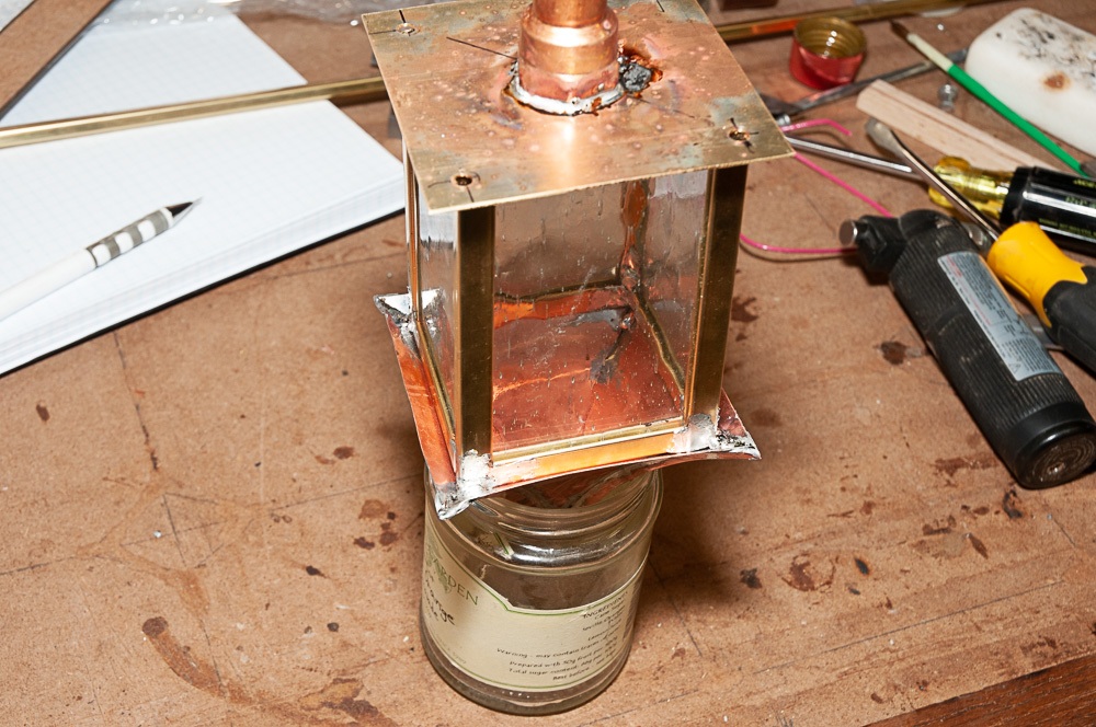
The next step is soldering the side panel assembly to the top. A small jar serves to hold the inverted roof. The side assembly is then centered in it and soldered in place. The corners are tacked on each side to the previously tinned areas of the roof.
Next step is washing off all of the excess flux and the lights are ready for bead blasting and powder coating.
Full video of the process can be found at:
Next: Making the Roof