| Rudder
The rudder stuffing box installation was straight forward. It is located 6" from the transom on the centerline of the boat. The hole was marked and drilled from the inside (remember to subtract off hull thickness). I then drilled the center hole with a 1 3/4" Forstner bit. As usual it is an excellent metal finder and ran into a long stainless steel staple (vertically). I had to resharpen twice to get through. Simply filing the edges at the same angle as the original grind is sufficient. A hole saw would also work, and was used for the prop shaft and water pick up holes. Once the main hole was through the stuffing box was inserted and shimmed to center it. The bottom plate was held over the end and the bolt holes were marked on both top and bottom. The bolt holes were then drilled 1/2 way from both sides with a 7/16" bit. This way, angular error will not accumulate appreciably and a reasonable accurate hole results. The bottom plate was filed, sanded and polished to give a nice appearance. A 3mm shim was required (plywood scrap) under the stuffing box to get the bottom edge flush with the plate. The holes ere epoxy coated and then the whole works was bedded in 3M 5200 compound. Extra was placed near the bolt holes and under the bolt heads to give a good seal. Bronze bolts, washers and Nylock nuts were used. As a nice touch all of the underwater screw slots are oriented fore and aft. |

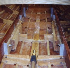
Rudder stuffing box and strut, prop shaft strut backing plate. Notch in stringer is for gas tank support piece. |
|
Prop Shaft holes Prop Shaft Measurements and Calculations (new) This was the worrisome one!. The Forstner bit was too short. No 3/8" drill extensions were to be found. I did not want to use a spade (Irwin type) bit and extension due to tear-out and lack of centering. My neighbor works for Milwaukee Tools and after consulting the gurus there came to the rescue! Many thanks to the folks at Milwaukee tools Milwaukee makes a quick change hole saw set with hex shank and a hex shank extension. This worked beautifully. A angle set-up block (12" scrap of 2x6) was predrilled at 16° and double stick taped in place. This was also weighted down by my son. This located the starting point and prevented the drill from skittering sideways as the hole was started. The prop shaft strut was placed along side and used as the angular reference. Drill to the max depth of the hole saw, backing out to clear the saw dist and prevent overheating frequently. Next switch to Forstner or spade bit to hog out the center slug. I tried the Milwaukee Self-Feed bits, but they were too aggressive and hard to control in the limited space. Switch back to the hole saw and proceed. Hog out again and repeat until you are through. It took less then 15 minutes to do the hole! DO NOT second guess on the angle. It is very shallow. I ended up with a "downward curved hole" when the prop shaft was inserted and it bound. It was cleaned up with the hole saw. I do not think that the correction would have been possible with another bit. There was no tear out or pealing of the fiberglass on the bottom. Sand the hole with a sanding drum. Coat with epoxy (3 times) and paint. |
|
| Strut installation
The strut is located and position checked by running the prop shaft through the strut and the stuffing box. The stuffing box to shaft opening was shimmed to center it (4mm plywood strips). Clearance was checked in the hull hole (actually prior to coating and painting). A backing plate was made to match the strut hole pattern. The holes were 1/2 drilled from each side. I VERY carefully drilled the first hole all of the way through and then used it to locate the backing plate and mark the holes. The strut was bedded in 3M 5200 and through bolted with bronze bolts and Nylock nuts. Drawings and dimensions to follow |
|
| Water Pick up
The water pickup is recommended to be 12-14" outboard of the strut in the directions. This places it right under the stringer!. Play with the placement as you need to install a backing block and be able to thread a valve on. There is not much room. I took the time to "French in" or recess the sea strainer scoop so that its flange is flush with the bottom of the hull. This was done with a razor knife and chisels. Make it ~1/16" deeper than the thickness of the flange to allow for epoxy coating and bedding compound. It was also filed, and sand to 150 grit. It looks very nice in place and now provides a small profile to catch on the trailer bunks. It is bedded in 3M 5200 also. |
|
| Engine Installation
Many measurements were made and calculated. The engine mounts were centered in their travel range. Engine bed logs ware made by ripping and gluing up 6" wide pieces of 3/4 " fir plywood. These were epoxied together and stacked 4 pieces wide to match the width requirements of the engine mounts. The bed logs were fitted around the frame members and the center aluminum angel bracket Ls were trimmed off. With the Sea Maxx engine and PCM transmission the engine bed logs are set level. Everything was epoxied in place with the bolts providing clamping pressure The engine mounts are through bolted both vertically and horizontally. Extra horizontal bolts bracketing the vertical bolts are also used to prevent the plywood lams from splitting apart. 6" 3/8" Stainless steel bolts with fender washers on each side, lock washers and nuts were used for mounting. The fender washers are relatively thick and nicely spread out the compressive force. Trailer wheels were removed and 2x6 blocks ware placed under the axles at the spring mounting points. This lowered the trailer and gave more maneuvering room for the engine hoist. The fender was also removed. With the Northern Tools 2 Ton hoist that I have the boom had to be all the way extended and the hoist jockeyed around the wheel bearing to line the motor up. We only had to pull it 3/8" additionally over. Hoisting in the engine had us worried. The floor was swept. Extra materials and tools were removed. The crew was told what to do and knew where to run (and had a clear path) if the thing let go. No one was to try and stop the engine if it started to fall. The hoist rolls very poorly with the engine lifted. It took 4 people to push it into place and a crow bar was used for fine motion as well as getting over the concrete floor expansion joints. We moved it up to the boat with the boom lowered, only raising it as we had to clear the side of the boat. In the end, it went smoothly. Everything lined up and the shaft was within <1/4" of mating in all directions. |
Engine beds in place. Note notches for motor mounts Prop shaft and stuffing box in foreground
Engine on hoist - starting to lift
Engine going up...
Almost up over the edge... |

Engine over the edge. Note prop shaft flange of down angle transmission.
Engine in!
|
|
| Next: Engine and Mechanical Connections Part II | |
| Home | Top |


