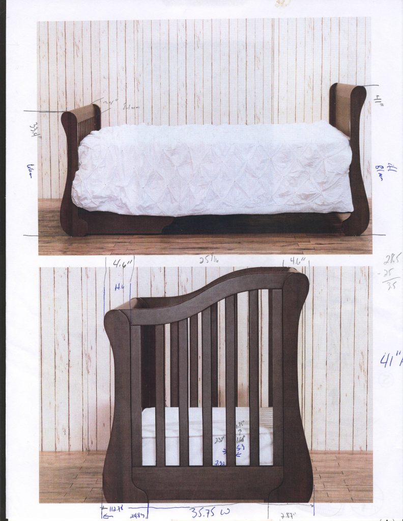
Now that we have a starting point for the design, it is time to start gathering dimensions from the photos. Traditionally, I have done this by printing photos at half or full sheet and then scaling it manually. My goal when borrowing from an existing design is not an exact replica but rather using the original as a model to start for overall proportions. I am not into doing reproductions. Additionally, in this case I am making improvements in the design.
First, I will note the major known dimensions. In this case it is overall height width and depth. This is done on each photo. Do not assume (or forget) that the scaling will be different in each image. Next the actual size in the photo for these is measured and the scaling amount calculated. I will normally do the actual measurements in mm to make the math easier (avoiding fractions). You can use a caliper or ruler – I like using a caliper.
I double check that the X&Y dimensions yield similar results. If all you have is an angled or isometric view then this gets more complicated. Now I take measurements of measured features and do the math in a spreadsheet so I have a listing of my measurements and can easily double check for errors in case of a conflict. I will also do the actual photo measurements in one color and the final scaled in another to avoid mix-ups
I will typically start on paper and make sure that the dimensions make some sense before transferring to Sketchup.
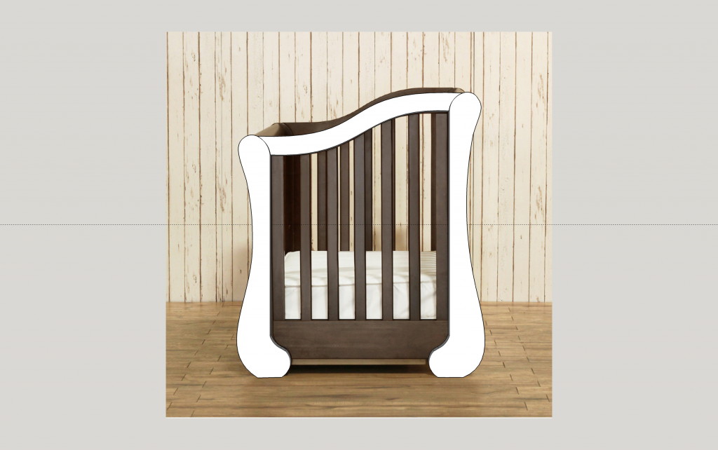
You can also import a photo into sketchup and then start drawing your components on top of it. For rectilinear pieces it is better to use it to set a few lines and then draw as you normally would. Trying to match the photo underneath will otherwise lead to errors and out of parallel edges.
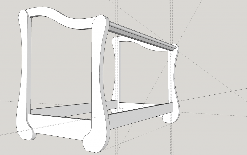
Here I have started with the curved end pieces. With the rudimentary curve drawing tools in Sketchup (arcs, lines and bezier curves) it took a lot of tries to get something that looked decent. I wish I could have gotten the NURBS lines to work which offer much more control. At this point I will lay down a couple of lines to mark the lower rails and then hide the photo. So now I can move into 3D space. each of the parts show becomes a component so I can mirror them for the other end and all of the modifications transfer as I work back and forth.
The top and bottom rails are then fit to the end posts. Now I mirror the ends, and set them approximately the right distance apart. I am still not sure if the end top and bottom rails will fully or partially overlap the legs.
Next come the bottom rails and I then draw guide lines up the leg posts to show where the top rail should line up vertically and the offset for the spindles from the inside edge. The inside spacing is an important dimension as you are only allowed 28 +-5/8″ by CPSC guidelines so you don’t have too big a gap around a standard crib mattress.
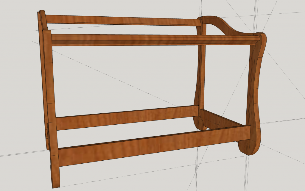
The front top rail is next. It took a few tries to get something that is not too thick. I may still make it a bit taller. Lets see after the rear top rail is in place. 
Now with the the back rail placed, and the frame colorized you can see the shapes better. I think it looks better with the taller top rails, but lest see what the girls say tomorrow.


